
Mod Guide: Induction and Exhaust (PLEASE READ BEFORE POSTING)
 02-15-2004, 11:10 AM
#1

Preface:
The LS1 like any other engine works as a system, treat is as one, you want to get as much air in and out as you can. The plethora of mods out there will allow you to do that. Things to consider before you start on your modding process:
1) There is no "best" part when it comes to mods.
2) When you want to start modding your car come up with a tangible plan.
3) Do not go into modding blindly; you will end up wasting money, time, and effort.
4) Do your research before you buy mods.
5) Find out your states/counties emissions requirements before choosing mods
6) Be realistic on what your going to do with your car
7) Usable power under the curve is what you want to shoot for, do not just look at peak gains
8) Work within your budget
9) If your are still under warranty Contact your own dealership and discuss your warranty and modding issues.
(Credit given where applicable. Info/pics taken from personal experience, around the Internet, and ls1tech/ls2.com)
II Exhaust
A. Catbacks
What they are: Bassani Borla Corsa Hooker Magnaflow Random Tech Loud Mouth LM w/ quad tip center mount SLP Dual/Dual GMMG Mufflex
What they do: increase exhaust flow and alter sound
What to look for: depends on what kind of look and sound your going for. The premier ls1 sounds site here. Spend alot of time listening to the setups and hear as many setups in person as you can. Exhaust is subjective, so get what you like best in terms of sound since its you who are going to be driving the car around.
- Straight through setups like LM and magnaflow (pt# 14267 for just the muffler) are regarded as some of the top flowing catbacks. Flowmaster is one of the worst flowing catbacks for the LS1, it does sound good in its defense. Hooker, Magnaflow, SLP D/D are all great budget cat backs; Corsa, Borla, and GMMG round out the top of the premium spectrum.
- Loudmouth: LM is a love/hate exhaust, it sounds great on stock manifolds with few bolts on's. When you start adding LT's and ORY's it shows its ugly side. LM + ORY + LT = rasp and drone. Try and listen to various LM setups in person to know what your getting into. Time after time people get LM and end up swapping it out since they get tired of its annoyances. To reduce the rasp and drone you have a few options; install some cats, replace the resonator with a real muffler, or install a 12-18" dynomax bullet. This setup is referred to Dynomouth; Borlamouth is of the same concept but with Borla xr-1 mufflers.

- With the Introduction of the TSP Rumber you no longer have to hack up your LM as the system is basically dynomouth. (Pic 2)
How to install: Follow the instructions that came with the setup. Some tips:
- Use pipe cutters or a sawz-all to remove the old exhaust, cut at the over the axel pipe or muffler.
- A breaker bar comes in very handy, some of those old bolts and clamps are alot harder to get off then you think
- Use alot of penetrating oil (i.e WD40)
B. Headers
What they are: there are 3 styles of headers for the ls1:
1) Shorties: Easy to install, small power gain
2) Mid-length: Not too small, but not so long as to scrape if your car is lowered
3) Long-tube: Biggest and best. Will maximize power as well as exhaust noise
What they do: allow that great engine of an ls1 breath
What to look for:
- Decide which header is right for you. If you want to stay 100% smog legal you'll need to stay with Shorties only and make sure they have a CARB number.
- If you have an 00-02 car do not bother with shorties. They received a better-designed manifold and flow quite well actually for what they are. You will see minimal gain if any by switching to shorties. If you have a 98-99 car you'll gain some rwhp from shorties but it wont be much either.
- If you decide on shorties work your other mods around that aspect meaning if you decide for a future cam keep it small (220 duration or smaller).
- ANY headers besides shorties will require a new Y pipe.
- Mac Mid-lengths vs LT's. The whole Mid vs LT debate will continue to go on, I�ve learned macs can produce great numbers and are a viable option for alot of people. Mac makes headers for 98-99 and 01-02 cars; if you have an 00 car you will need the EGR pipes from a 98-99 car or you'll need to remove your EGR system.
-Macs and QTP LT�s side by side.
- When buying long tubes what you are paying for is fitment, quality, fit and finish. All LT's dyno within the same net gain. Swap from one brand to another for the sole purpose of gains and you'll be disappointed. 1 3/4 sized primaries are more then adequate for stock cubes. If you have a stroker look into some 1 7/8 primaried headers. If you have a high power stock cubed setup you might want to look into a 1 � stepped to 1 7/8.
- Buy your headers with some kind of ceramic coating or get stainless steel. If you cant afford coated headers hold off until you can. If your car see's alot of winters (real winters; i.e. east coast and mid west, ect) you might want to seriously consider the stainless steel headers, they are more expensive then ceramic coated headers but the chance of rust will be greatly diminished.
- If you plan to lower or are lowered then any long tube other then SLP will tuck pretty nicely.
Long Tubes
Since Long Tubes are by far the most popular headers they receive the most questions; to a certain extent the old adage of "You get what you pay for" rings true. Info on a few of the more popular choices, not all the long tubes available by no means.
Pacesetters: Extremely popular due to there price, coated they can be had for under 400 dollars. Quality is very good for what your spending your money on, welds and collector are good. If you�re on a budget and want LT's then Pacesetters should be at the top of your list. Mid production cycle Pacesetter improved on some of the fitment issues people were having with the k-member and banging.
Jet Hot/Hookers: The Hooker and Jet Hot Long Tubes are of the same design, jet hot took the hooker design and improved upon it a bit by moving the o2 bungs on the inside of the headers and they use a thicker tubing and have thicker flanges. Both are great long tubes and will run you 500-600 bucks.
QTP/kooks: Both Kooks and QTP are stainless steel headers, and are generally regarded as the cream of the crop. Quality is top notch and they can be polished for that bling look if you'd like. There only draw back is the price, at 700+ they are not for everyone. If you have the money or are the kind of person who wants the best then kooks or qtp is what you want. As far as kooks vs qtp get whichever one is cheaper.
SLP: SLP's are the long tube that usually sparks some debate. Alot of newbies are drawn into them because of the hp claims slp makes. But as already stated all LT's dyno within the same range so SLP's claims are moot. From a quality stand point they are a great header; stainless steel and are ceramic coated. There major drawback is installation and there ground clearance, or lack there of. If you plan to lower your car then pass on the SLP's or learn to change your driving style or else you'll endure alot of scrapping. Another drawback is the price as they are 700+. (My personal opinion, if you�re going to spend 700+ on headers then go for the kooks/qtp)
The LS1 like any other engine works as a system, treat is as one, you want to get as much air in and out as you can. The plethora of mods out there will allow you to do that. Things to consider before you start on your modding process:
1) There is no "best" part when it comes to mods.
2) When you want to start modding your car come up with a tangible plan.
3) Do not go into modding blindly; you will end up wasting money, time, and effort.
4) Do your research before you buy mods.
5) Find out your states/counties emissions requirements before choosing mods
6) Be realistic on what your going to do with your car
7) Usable power under the curve is what you want to shoot for, do not just look at peak gains
8) Work within your budget
9) If your are still under warranty Contact your own dealership and discuss your warranty and modding issues.
(Credit given where applicable. Info/pics taken from personal experience, around the Internet, and ls1tech/ls2.com)
II Exhaust
A. Catbacks
What they are: Bassani Borla Corsa Hooker Magnaflow Random Tech Loud Mouth LM w/ quad tip center mount SLP Dual/Dual GMMG Mufflex
What they do: increase exhaust flow and alter sound
What to look for: depends on what kind of look and sound your going for. The premier ls1 sounds site here. Spend alot of time listening to the setups and hear as many setups in person as you can. Exhaust is subjective, so get what you like best in terms of sound since its you who are going to be driving the car around.
- Straight through setups like LM and magnaflow (pt# 14267 for just the muffler) are regarded as some of the top flowing catbacks. Flowmaster is one of the worst flowing catbacks for the LS1, it does sound good in its defense. Hooker, Magnaflow, SLP D/D are all great budget cat backs; Corsa, Borla, and GMMG round out the top of the premium spectrum.
- Loudmouth: LM is a love/hate exhaust, it sounds great on stock manifolds with few bolts on's. When you start adding LT's and ORY's it shows its ugly side. LM + ORY + LT = rasp and drone. Try and listen to various LM setups in person to know what your getting into. Time after time people get LM and end up swapping it out since they get tired of its annoyances. To reduce the rasp and drone you have a few options; install some cats, replace the resonator with a real muffler, or install a 12-18" dynomax bullet. This setup is referred to Dynomouth; Borlamouth is of the same concept but with Borla xr-1 mufflers.
- With the Introduction of the TSP Rumber you no longer have to hack up your LM as the system is basically dynomouth. (Pic 2)
How to install: Follow the instructions that came with the setup. Some tips:
- Use pipe cutters or a sawz-all to remove the old exhaust, cut at the over the axel pipe or muffler.
- A breaker bar comes in very handy, some of those old bolts and clamps are alot harder to get off then you think
- Use alot of penetrating oil (i.e WD40)
B. Headers
What they are: there are 3 styles of headers for the ls1:
1) Shorties: Easy to install, small power gain
2) Mid-length: Not too small, but not so long as to scrape if your car is lowered
3) Long-tube: Biggest and best. Will maximize power as well as exhaust noise
What they do: allow that great engine of an ls1 breath
What to look for:
- Decide which header is right for you. If you want to stay 100% smog legal you'll need to stay with Shorties only and make sure they have a CARB number.
- If you have an 00-02 car do not bother with shorties. They received a better-designed manifold and flow quite well actually for what they are. You will see minimal gain if any by switching to shorties. If you have a 98-99 car you'll gain some rwhp from shorties but it wont be much either.
- If you decide on shorties work your other mods around that aspect meaning if you decide for a future cam keep it small (220 duration or smaller).
- ANY headers besides shorties will require a new Y pipe.
- Mac Mid-lengths vs LT's. The whole Mid vs LT debate will continue to go on, I�ve learned macs can produce great numbers and are a viable option for alot of people. Mac makes headers for 98-99 and 01-02 cars; if you have an 00 car you will need the EGR pipes from a 98-99 car or you'll need to remove your EGR system.
-Macs and QTP LT�s side by side.
- When buying long tubes what you are paying for is fitment, quality, fit and finish. All LT's dyno within the same net gain. Swap from one brand to another for the sole purpose of gains and you'll be disappointed. 1 3/4 sized primaries are more then adequate for stock cubes. If you have a stroker look into some 1 7/8 primaried headers. If you have a high power stock cubed setup you might want to look into a 1 � stepped to 1 7/8.
- Buy your headers with some kind of ceramic coating or get stainless steel. If you cant afford coated headers hold off until you can. If your car see's alot of winters (real winters; i.e. east coast and mid west, ect) you might want to seriously consider the stainless steel headers, they are more expensive then ceramic coated headers but the chance of rust will be greatly diminished.
- If you plan to lower or are lowered then any long tube other then SLP will tuck pretty nicely.
Long Tubes
Since Long Tubes are by far the most popular headers they receive the most questions; to a certain extent the old adage of "You get what you pay for" rings true. Info on a few of the more popular choices, not all the long tubes available by no means.
Pacesetters: Extremely popular due to there price, coated they can be had for under 400 dollars. Quality is very good for what your spending your money on, welds and collector are good. If you�re on a budget and want LT's then Pacesetters should be at the top of your list. Mid production cycle Pacesetter improved on some of the fitment issues people were having with the k-member and banging.
Jet Hot/Hookers: The Hooker and Jet Hot Long Tubes are of the same design, jet hot took the hooker design and improved upon it a bit by moving the o2 bungs on the inside of the headers and they use a thicker tubing and have thicker flanges. Both are great long tubes and will run you 500-600 bucks.
QTP/kooks: Both Kooks and QTP are stainless steel headers, and are generally regarded as the cream of the crop. Quality is top notch and they can be polished for that bling look if you'd like. There only draw back is the price, at 700+ they are not for everyone. If you have the money or are the kind of person who wants the best then kooks or qtp is what you want. As far as kooks vs qtp get whichever one is cheaper.
SLP: SLP's are the long tube that usually sparks some debate. Alot of newbies are drawn into them because of the hp claims slp makes. But as already stated all LT's dyno within the same range so SLP's claims are moot. From a quality stand point they are a great header; stainless steel and are ceramic coated. There major drawback is installation and there ground clearance, or lack there of. If you plan to lower your car then pass on the SLP's or learn to change your driving style or else you'll endure alot of scrapping. Another drawback is the price as they are 700+. (My personal opinion, if you�re going to spend 700+ on headers then go for the kooks/qtp)
Last edited by jrp; 05-28-2005 at 06:18 PM.
 02-15-2004, 11:11 AM
#2
FLP: At first glance alot of people are turned off on the FLP setup because of the price. What you have to understand is the FLP setup comes as a kit with the ceramic-coated headers, Y pipe, cats, and off road pipes. When you look at it from that perspective it�s a great deal and setup. The biggest advance the FLP system has is the ability to swap from cats to off road pipes and vise versa at will. Great for guys who want to run off-road pipes and then need to swap to cats for emissions requirements.
Flowtech: When engeneering the Flowtech headers the premise was to build a Hooker set using half the budget; it shows. The welds, and flanges are very thin and the primaries have a dent in them to �clear� the k-member. Even with the �clearance dent� people are still having issues. Because of the low quality TPS has stopped carrying the Flowtech line of LT�s. If you need a budget header look into the new Pacesetter design or spend the dough on hooker/jet hots.
Others available but not reviewed:
-Thunder Racing Headers
-Dynatech
-Stainless Works
-PPC
-SuperMaxx
-TTS
How to install: Flat out, install will vary from car to car and from the type of header you choose, some are easier to install then others.
- Great Pacesetter install guide done by foff667
- SLP guide (done by bomax if i recall)
- Mac Mid's Guide
- Awesome writeup by DirtyJohn! QTP LT's + TSP duals: Install and review.
A few install tips:
- Patience; if after working for several hours without any apparent results take a break. Things often have a way of working out coming back from a fresh start.
- A breaker bar is your friend.
- All LT's go in from the bottom.
- The stock cat bolts will often break, especially on the older 98-99 cars, don�t worry about it.
- Use plenty of penetrating oil on all the cat to manifold bolts.
- Have a buddy/wife/gf help you out when need be.
- Remove the oil diverter for a bit more room on the drivers side install.
- May or may not have to knotch the K-member and floor board clearance (CamaroCain).
- Steering shaft removal may or may not be required. (For my install I couldn�t get the damn thing to budge, so I used a die grinder to grind down the block tab to get the drivers side header to slide up). Heed the warning on the steering shaft before removal.
- Have all the proper tools before the outset of installation; jack/jack stands and/or ramps, basic hand tools (3/8, 1/2 drive ratchet, 10mm, 12mm, 15mm, ect sockets), hammer. Optional but very handy tools that may or may not be needed; sawz-all, die grinder, 2x4 4x4 pieces of wood and/or some bricks.
- Get the car as high as safely possible. It's alot higher then you think. (During my own install I had the rear on ramps and the front was propped up with my jack on a 4x4 piece of wood to get the extra clearance need.)
- Don�t think it has to be mentioned but I�ll say it anyway; use safety goggles where applicable and make sure your car is secured on the ramp/jack stands before getting under the car and working on it. Basically don�t do any stupid ****
- Give yourself plenty of time to get the install done; first time around factor in 5-12hrs. Don�t worry if it takes you longer, just concentrate on getting it done right and gaining the experience
- Typical prices a shop will charge for an install are 300-500 dollars depending on location. If you have the time, you owe it to yourself to give the install a shot yourself. It�s not that hard and doesn�t require alot of technical knowledge or experience. If you run into trouble during the install come to the boards in a calm and collected manner and you'll get your answer in no time.
- Will you need tuning after headers: Every car varies, you wont know until the headers are installed and you've put some miles on the car. Headers usually cause the car to run a bit rich but its nothing stock tune cant handle. If you want full advantage of the new headers then you'll want a tune. Just plan accordingly; if you know your not going to install big mods (h/c) sometime in the near future then I�d go ahead and get a tune. If you plan for a new cam and/or heads then hold off on tuning for the headers and get a tune once the h/c is installed, it'll save you the time and money of having to tune twice. If you don�t want to pay for a full tune you can always pick up a used MAFT (mass air fuel translator) and dial in your A/F ratio a bit.
- Where to buy:
1) Pacesetters: TSP (http://www.texas-speed.com) has the best deals on pacesetters. And they are the only place to get the TSP Rumbler catback and dual setup
2) Kooks: Contact Matt from TTP (http://www.ttperformance.net/) you'll usually get the best deal from him.
3) Jet hot/hookers: Go to the sponsor forums, every so often there is a GP (group purchase) on jet hots and you can get a great price.
4) QTP: Contact Barry from QTP (http://www.quicktimeperformance.com/) and see what kind of price he can get you.
C. Y-Pipes
What they are: Jet hot catted/ory SLP stock replacement Y Mufflex Random Tech stock replacement catted Y Pacesetter ORY
- Catted Y denotes a Y with cats; ORY denotes a Y with no cats
What they do: Connect the headers to the catback and aid in exhaust flow provided it matches the rest of your system. Meaning keep the diameter relatively consistent, 3" is the most popular, a 2.5" is fine as well and will give you a bit more clearance if your lowered.
What to look for: Y pipes come in all different shapes and diameters, if you can, get the Y made by the same company that you got your headers from. Meaning if you get the Hooker LT's then get the hooker Y, ect. All Y pipes are not directly swappable. If you wish to use another manufactures Y for your setup you are most likely going to have to modify it to fit.
-Those looking to get Pacesetters; there Y is a toss up, some people's are "acceptable", others are straight ****. Pace didn�t put to much time or development into making a quality Y and it shows in the collector. Your best bet is to go with a custom Y or modify your Pace ORY like Larry did.
Those with Hooker/Jethot/Pacesetters can now rejoice, TSP has just come out with a 3� Catted Y pipe to fit your headers. They use high flow carsound cats. At 350 a pop you can rest assure that this is the Y-pipe you want to get. They also offer an ORY as well.
- A custom Y is great since its taylored to your exact setup and will allow you to get the best fitment and clearance. Just pick up a Flowmaster merge collector and cats if you need and have a shop fab up the rest; depending on shop it should run you 100-200 bucks not including parts (i.e. merge collector)
- Do Not invest in a new Y pipe unless you plan to stick with shorties/stock manifolds, and even at that it�s barely worth it since you'll gain practically nothing by a new Y on stock manifolds. If you buy a new Y for stock manifolds/shorties you'll need to replace the Y you just bought if you add LT's or mids in the future.
- If you need cats for emissions purposes then do not purchase an ORY and then try and weld cats in them, just spring for the catted Y or purchase some cats, flowmaster merge collector and have a shop fab the rest. Alot of ORY's don�t have enough room to accommodate cats. If you still want to try it then get the smallest cats you can; slp's or random tech.
- The '98-'99 Y-pipe won't work on a 2000-2002 because it doesn't have a flange on the passenger side pipe. It has to be welded in place. It took them till the 2000 model year to figure out it might be better to have both sides flanged and secured with bolts. (xtrooper)
- To Cure Y pipe banging mufflex has come up with this solution. 1, 2. You can purchase this from Thunder Racing.
Last edited by TheBlurLS1; 11-07-2006 at 05:02 PM.
02-15-2004, 11:13 AM
#3
D. Duals
What they are:
1) X-pipe setups 1 (South FL) 2 3 (DVST8OR) 4 (Y2KSS).
2) H-Pipe setup: 1 (Lanes)
What they do: See Y pipe
What to look for: Your only actual viable option is an X pipe or H pipe. Which is better will always be debated. Most people go with an X pipe, in a nutshell an X-pipe will net you more power and torque and an H-pipe will have a slightly better sound. Both are great, so choose what you like, either is better then a traditional Y setup. Where duals shine is power under the curve.
- When it comes to duals you have 2 options; dumped before the axel or going all the way out the back. The former is a more popular option because of cost. A complete dual setup dumped should run you 500 bucks or less. If you desire to go out the back it'll cost you, you'll need some custom over the axel work or you can go a cheaper route and go under the axel. Both have there advantages; dumped are very cost effective and have a great hp/$ ratio. However since the exhaust is now exiting under the car; cab noise is more prevalent, you'll notice rattles you never knew you had, and you'll feel the resonance. Duals out the back are more expensive but you'll get the hp and sound of the duals without the little annoyances of the dumped setup. (My advice would be to go with dumps first and see how you like it and whats acceptable to you, if you find the annoyances unbearable you can always complete the duals out the back, just pick up where the dumps left off and go over the axel or under.
- TSP has pretty much hit a home run with its new exhaust line, in addition to the Rumbler catback, Catted and ORY, they have introduced a direct fit bolt on True Duals. The system is a direct bolt on to the Hooker/Jethot/Pacesetter LT�s, others will work but you will need adjusting and fitting. The mufflers used are 18� Dynomax Bullets which offer a slightly more subdued sound over a 12� bullet. The setup runs around ~$430.
More pics of the TSP Duals:
- 1
- 2
- 3
- 4
- 5
- If you plan for dumps you can go 3" piping all through out. If you are lowered or plan to lower or want duals all the way back go with 2.5", you'll have more ground clearance and more room to allow for going over the axel depending on how you set it up. You can also go 3" up to the X pipe and then reduce to 2.5".
- Both 2.5" and 3" will support plenty of power, most likely more then you'll ever produce. Choose your piping based on fitment and clearance, not power.
- When you run duals you'll want an X/H pipe for the scavaging and equalizing effect, you wont get that from straight pipes off of the collector.
- True Duals w/ Side Pipes 1 2 (Rene - Trans Am WS6 RGS)
How to install: You have a few options:
- Have a shop fab up the whole setup for you
- Buy just an X/H pipe from jegs or summit and mufflers and have a shop fab the rest
- Buy a Dr. Gas kit and have a shop fab the rest
E. Cut-outs
What they are: Flowtech QTP electric cutout
What they do:
What to look for: An electric cutout is the best bet, you can be loud when you need/want it to be and quite when you need/want it to be all at the flip of a switch. A standard cut you you�ll need to get under the car to cap or uncap it. A cutout is a great mod for cheap horsepower and sound.
How/Where to install: For an electric cutout follow the wiring guide instructions. For both type of cutouts you'll need to have them welded in. You have a few options of placement. The easiest is the I-pipe as there is plenty of room. You can also run dual cutouts in place of where the cats would be (on a LT' setup). Dual cats and cutouts can be done but the fitment will be very close and you'll need to run some small cats.
F. Misc/Emissions

- Gaskets: Stick with the metal gaskets, either new or re-used. Don�t bother with the paper gaskets that often come with your headers, you'll just increase the chance of leaks.
-Header Bolts: Oem bolts are fine, again new or re-used. If you want to spend the money you can get some stage 8 locking bolts, they are not necessary though. Header bolts are only required to be torqued down to 18ft-lb's, which is not alot. Do Not over torque the bolts as you run the risk of stripping the threads on the heads. They are aluminum after all. Torque the bolts from the center out.
- Clamps: Invest in some good band clamps; they can be had from a variety of sponsors or found at your local parts store. U-bolt clamps are pieces of ****. Another option you have is to flange your system.
-If you�re using clamps and are still having exhaust leaks try buying some aluminum tape that can be found at Lowes or home depot. Wrap the tape around the collector; whether header or Y pipe, for thicker area for the clamp to seal up too.
- Cats: Magnaflow/Carsound cats are the best overall option; they flow great and can be had for a great price, especially on ebay.
1) You�ll want pt# 94106 for a 2.5" inlet/outlet and 94109 for a 3" inlet/out.
- o2 Extension and Sims: When buying Long tubes you'll need to get 2 o2 extensions to connect the front o2 sensors as the o2 bungs have now been moved so far down the sensor wont reach the connection. Most Y/X/H pipes do not have rear o2 provisions so you'll need to run 2 o2 Sims to prevent an SES light. You can also turn off the codes with edit/hp tuner/predator and bypass the need for the Sims.
1) DO NOT PUT O2 SIMS ON THE FRONT O2 SENSORS (B1S1) (B2S1). The pcm determines the A/F ratio from the front o2 sensors when it goes into closed loop.
I. Emission
1) When buying headers you have the option to buy them with or without emissions provisions. Find out your states/counties emissions standards before buying.
2) If you know your emissions requirements you can buy whichever setup meets your needs.
3) If your state only has OBDII testing you may remove your Air and/or EGR setup (only 98-00 cars have EGR). You can purchase the racing headers and get rid of the above systems. As long as you arent throwing any codes you will pass the OBDII test.
4) If your car has a sniffer/visual test you'll need to decide how you want to play it; either comply with the rules and keep your Air/Egr and purchase the headers with the emissions provisions or try and find a shop that will over look those missing systems.
5) 9 times out of 10 you will not pass the sniffer test without cats.
6) Go here (bomax) to remove your Air/Egr. 00-02 cars go here
7) If you want to swap 98-99 and 00-02 headers around you'll need to remove your Air system or purchases the Air tubes from the year the headers were made for since the 98-99 and 00-02 have different Air tube setup.
8) It should go without saying but if you want to swap 01-02 headers on your 98-00 you'll need to remove you EGR system.
9) 00 are an oddball year as the EGR and Air setups are different then the 98-99.
10) When removing the Air system on the 00+ cars you'll be left with a vacuum hose that you'll need to plug up.
11) Removing your Air/EGR/rear o2's will set off an SES light but will not effect performance at all.
12) If you plan to keep your Air system with your LT's you'll want to run Air Restrictor plates (bomax)
What they are:
1) X-pipe setups 1 (South FL) 2 3 (DVST8OR) 4 (Y2KSS).
2) H-Pipe setup: 1 (Lanes)
What they do: See Y pipe
What to look for: Your only actual viable option is an X pipe or H pipe. Which is better will always be debated. Most people go with an X pipe, in a nutshell an X-pipe will net you more power and torque and an H-pipe will have a slightly better sound. Both are great, so choose what you like, either is better then a traditional Y setup. Where duals shine is power under the curve.
- When it comes to duals you have 2 options; dumped before the axel or going all the way out the back. The former is a more popular option because of cost. A complete dual setup dumped should run you 500 bucks or less. If you desire to go out the back it'll cost you, you'll need some custom over the axel work or you can go a cheaper route and go under the axel. Both have there advantages; dumped are very cost effective and have a great hp/$ ratio. However since the exhaust is now exiting under the car; cab noise is more prevalent, you'll notice rattles you never knew you had, and you'll feel the resonance. Duals out the back are more expensive but you'll get the hp and sound of the duals without the little annoyances of the dumped setup. (My advice would be to go with dumps first and see how you like it and whats acceptable to you, if you find the annoyances unbearable you can always complete the duals out the back, just pick up where the dumps left off and go over the axel or under.
- TSP has pretty much hit a home run with its new exhaust line, in addition to the Rumbler catback, Catted and ORY, they have introduced a direct fit bolt on True Duals. The system is a direct bolt on to the Hooker/Jethot/Pacesetter LT�s, others will work but you will need adjusting and fitting. The mufflers used are 18� Dynomax Bullets which offer a slightly more subdued sound over a 12� bullet. The setup runs around ~$430.
More pics of the TSP Duals:
- 1
- 2
- 3
- 4
- 5
- If you plan for dumps you can go 3" piping all through out. If you are lowered or plan to lower or want duals all the way back go with 2.5", you'll have more ground clearance and more room to allow for going over the axel depending on how you set it up. You can also go 3" up to the X pipe and then reduce to 2.5".
- Both 2.5" and 3" will support plenty of power, most likely more then you'll ever produce. Choose your piping based on fitment and clearance, not power.
- When you run duals you'll want an X/H pipe for the scavaging and equalizing effect, you wont get that from straight pipes off of the collector.
- True Duals w/ Side Pipes 1 2 (Rene - Trans Am WS6 RGS)
How to install: You have a few options:
- Have a shop fab up the whole setup for you
- Buy just an X/H pipe from jegs or summit and mufflers and have a shop fab the rest
- Buy a Dr. Gas kit and have a shop fab the rest
E. Cut-outs
What they are: Flowtech QTP electric cutout
What they do:
What to look for: An electric cutout is the best bet, you can be loud when you need/want it to be and quite when you need/want it to be all at the flip of a switch. A standard cut you you�ll need to get under the car to cap or uncap it. A cutout is a great mod for cheap horsepower and sound.
How/Where to install: For an electric cutout follow the wiring guide instructions. For both type of cutouts you'll need to have them welded in. You have a few options of placement. The easiest is the I-pipe as there is plenty of room. You can also run dual cutouts in place of where the cats would be (on a LT' setup). Dual cats and cutouts can be done but the fitment will be very close and you'll need to run some small cats.
F. Misc/Emissions
- Gaskets: Stick with the metal gaskets, either new or re-used. Don�t bother with the paper gaskets that often come with your headers, you'll just increase the chance of leaks.
-Header Bolts: Oem bolts are fine, again new or re-used. If you want to spend the money you can get some stage 8 locking bolts, they are not necessary though. Header bolts are only required to be torqued down to 18ft-lb's, which is not alot. Do Not over torque the bolts as you run the risk of stripping the threads on the heads. They are aluminum after all. Torque the bolts from the center out.
- Clamps: Invest in some good band clamps; they can be had from a variety of sponsors or found at your local parts store. U-bolt clamps are pieces of ****. Another option you have is to flange your system.
-If you�re using clamps and are still having exhaust leaks try buying some aluminum tape that can be found at Lowes or home depot. Wrap the tape around the collector; whether header or Y pipe, for thicker area for the clamp to seal up too.
- Cats: Magnaflow/Carsound cats are the best overall option; they flow great and can be had for a great price, especially on ebay.
1) You�ll want pt# 94106 for a 2.5" inlet/outlet and 94109 for a 3" inlet/out.
- o2 Extension and Sims: When buying Long tubes you'll need to get 2 o2 extensions to connect the front o2 sensors as the o2 bungs have now been moved so far down the sensor wont reach the connection. Most Y/X/H pipes do not have rear o2 provisions so you'll need to run 2 o2 Sims to prevent an SES light. You can also turn off the codes with edit/hp tuner/predator and bypass the need for the Sims.
1) DO NOT PUT O2 SIMS ON THE FRONT O2 SENSORS (B1S1) (B2S1). The pcm determines the A/F ratio from the front o2 sensors when it goes into closed loop.
I. Emission
1) When buying headers you have the option to buy them with or without emissions provisions. Find out your states/counties emissions standards before buying.
2) If you know your emissions requirements you can buy whichever setup meets your needs.
3) If your state only has OBDII testing you may remove your Air and/or EGR setup (only 98-00 cars have EGR). You can purchase the racing headers and get rid of the above systems. As long as you arent throwing any codes you will pass the OBDII test.
4) If your car has a sniffer/visual test you'll need to decide how you want to play it; either comply with the rules and keep your Air/Egr and purchase the headers with the emissions provisions or try and find a shop that will over look those missing systems.
5) 9 times out of 10 you will not pass the sniffer test without cats.
6) Go here (bomax) to remove your Air/Egr. 00-02 cars go here
7) If you want to swap 98-99 and 00-02 headers around you'll need to remove your Air system or purchases the Air tubes from the year the headers were made for since the 98-99 and 00-02 have different Air tube setup.
8) It should go without saying but if you want to swap 01-02 headers on your 98-00 you'll need to remove you EGR system.
9) 00 are an oddball year as the EGR and Air setups are different then the 98-99.
10) When removing the Air system on the 00+ cars you'll be left with a vacuum hose that you'll need to plug up.
11) Removing your Air/EGR/rear o2's will set off an SES light but will not effect performance at all.
12) If you plan to keep your Air system with your LT's you'll want to run Air Restrictor plates (bomax)
Last edited by jrp; 07-04-2005 at 12:14 AM.
02-15-2004, 04:44 PM
#4
I. Intake
A. Lids:
What they are:
What they do: increase airflow and thus horse power
What to look for: a lid is a lid is a lid. They will all net you the same horsepower. Pick your lid based on looks and price.
- 00+ cars will need to use an air breather which is required for lids that do not that the provision on the lid. Air breathers can be had from a variety of sponsors.
How to install: http://www.installuniversity.com/ins...id_install.htm
B. Filters:
What they are:

What they do: larger surface area increases airflow and thus more power.
What to look for: k&n/powershot filters have shown little gains on the ls1; there retaining quality is the ability to clean them and re-use them
How to install: if you can�t figure it out sell your car
C. Bellows:
What they are: slp fernco bakerhose airflow system
What they do: straighten out the airflow
What to look for: an appearance mod. Chalk it up to the every little bit helps category in terms of "performance". Fernco can be bought at your local home depot or Lowes. The size you want is 3"x3", it is in the plumbing department.
How to install: see filter installation
- Tips: if buying a ferco, bakerhose, airflow systems bellow cutting and fitting may be required. Heat up the tubing in the microwave to soften up the material for easier cutting and fitting. It will also prevent the stiff bellow from cracking or loosening up your lid.
- Pretty good deal here...
Less than $6 for a smooth bellows.
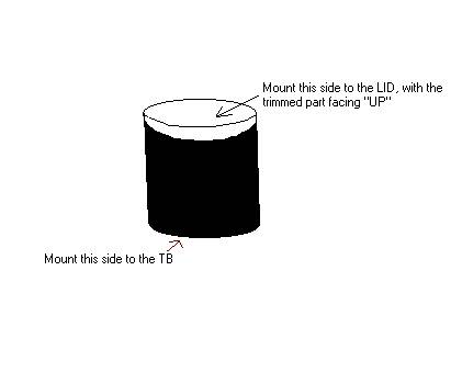
Step one: Go to home depot and buy a 3"x3" Fernco rubber coupling.. It should be around $5-6.
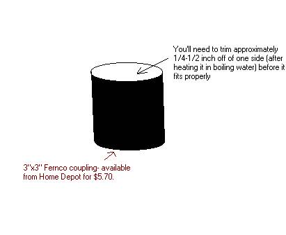
Then Proceed to remove all clamps and labeling, and put it in boiling water for about 10 minutes to soften the rubber. After softening, trim approximately 1/4" to 1/2" off of ONE side of the coupling to make a better fit.
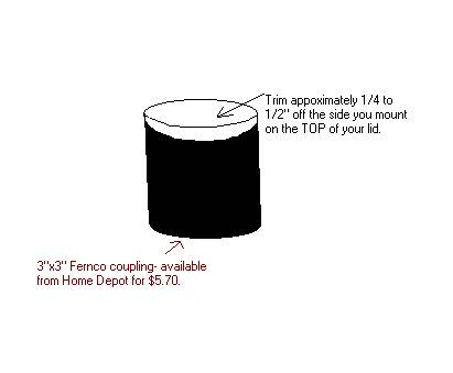
After you've trimmed it and are satisfied with it, put it back in the hot water for 5-10 minutes. Otherwise you'll have trouble getting one end over the throttle body.
I did this, because I originally had my nitrous nozzle in the bellows, and now i'm spraying in the airbox.
Hope this helps someone, because it took me almost an hour to put it all together (the info) The job only takes about 15 minutes.
Matt (Ole1830)
D. Maf:
What they are:
What they do: "...Aftermarket mafs, don't make power, due to larger size, they make power, by tricking the computer into seeing less air, therefore the computer gives more timing, and less fuel..." (Ryan 'slow')
What to look for: PORT/SWAP/DE-SCREEN AT YOUR OWN RISK. The stock maf is good for 500hp. If by chance your maxing out your MAF contact your tuner and see what he/she recommends.
How to install: http://www.installuniversity.com/ins.../mafh_swap.htm
E. TB:
What they are:
What they do: increase airflow
What to look for: look into Bo White, Cammin BeaSST, shaner (s2/s3), and bauer. They all make great ported throttle bodies.
- The '98-'99 F-body throttle bodies have a smaller cam compared to the '00-'02 F-body TB's
- The smaller radius throttle cam opens the throttle plate faster
How to install: http://www.installuniversity.com/ins...ar/tb_swap.htm
F. Intake Manifold:
What they are: SLP Ls6 w/ egr provision Holley LSX
What to look for: the ls6 intake will serve a great majority of setups. All 01-02 cars already have an ls6 intake. If you have a 98-00 and want to do an ls6 swap you'll need the new ls6 coolant tubes and plugs. If you have a stroker or are the kind of person who wants all the horsepower they can get look into the LSX.
- the 78mm LSX has shown marginal improvements over the ls6 intake and quite frankly not worth the swap. Stay with the ls6 intake or upgrade to the 90/90 setup
- Intake Manifold Test. Flow tests all the the popular intakes and some carb style as well.
- LSX dyno results.
- The Ls6 intake has many different part numbers buts its the same intake
- The only way to tell 100% if you are buying an ls6 intake, especially used is to ask for pics of the bottom. The vette LS1 intake does not have an EGR provision so its easy to pass that off as an LS6 if you are none the wiser. The difference between the LS1 and LS6 intakes can be see here; the ls1 intake is on the left and the ls6 is on the right.
How to install: http://www.ls1howto.com/index.php?article=5
G. CAI
What they are: FTRA SSRA: (1)(2)(3) BGRA
What they do: take in cold air from the bottom/front of the car
What to look for: fast toys ram air (FTRA) and super sucker ram air (SSRA) are to very popular choices. BGRA is an option for you ws6 hood guys. Either option you choice you'll want the air box sealed.
How to install: follow the provided instructions that come with the setup.
H. FIPK:
What they are:
What they do: same effect as the lid.
What to look for: a ws6 hood or slp z hood with functionality is bests suited for maximum airflow.
How to install: see CAI install.
A. Lids:
What they are:
What they do: increase airflow and thus horse power
What to look for: a lid is a lid is a lid. They will all net you the same horsepower. Pick your lid based on looks and price.
- 00+ cars will need to use an air breather which is required for lids that do not that the provision on the lid. Air breathers can be had from a variety of sponsors.
How to install: http://www.installuniversity.com/ins...id_install.htm
B. Filters:
What they are:
What they do: larger surface area increases airflow and thus more power.
What to look for: k&n/powershot filters have shown little gains on the ls1; there retaining quality is the ability to clean them and re-use them
How to install: if you can�t figure it out sell your car
C. Bellows:
What they are: slp fernco bakerhose airflow system
What they do: straighten out the airflow
What to look for: an appearance mod. Chalk it up to the every little bit helps category in terms of "performance". Fernco can be bought at your local home depot or Lowes. The size you want is 3"x3", it is in the plumbing department.
How to install: see filter installation
- Tips: if buying a ferco, bakerhose, airflow systems bellow cutting and fitting may be required. Heat up the tubing in the microwave to soften up the material for easier cutting and fitting. It will also prevent the stiff bellow from cracking or loosening up your lid.
- Pretty good deal here...
Less than $6 for a smooth bellows.
Step one: Go to home depot and buy a 3"x3" Fernco rubber coupling.. It should be around $5-6.
Then Proceed to remove all clamps and labeling, and put it in boiling water for about 10 minutes to soften the rubber. After softening, trim approximately 1/4" to 1/2" off of ONE side of the coupling to make a better fit.
After you've trimmed it and are satisfied with it, put it back in the hot water for 5-10 minutes. Otherwise you'll have trouble getting one end over the throttle body.
I did this, because I originally had my nitrous nozzle in the bellows, and now i'm spraying in the airbox.
Hope this helps someone, because it took me almost an hour to put it all together (the info) The job only takes about 15 minutes.
Matt (Ole1830)
D. Maf:
What they are:
What they do: "...Aftermarket mafs, don't make power, due to larger size, they make power, by tricking the computer into seeing less air, therefore the computer gives more timing, and less fuel..." (Ryan 'slow')
What to look for: PORT/SWAP/DE-SCREEN AT YOUR OWN RISK. The stock maf is good for 500hp. If by chance your maxing out your MAF contact your tuner and see what he/she recommends.
How to install: http://www.installuniversity.com/ins.../mafh_swap.htm
E. TB:
What they are:
What they do: increase airflow
What to look for: look into Bo White, Cammin BeaSST, shaner (s2/s3), and bauer. They all make great ported throttle bodies.
- The '98-'99 F-body throttle bodies have a smaller cam compared to the '00-'02 F-body TB's
- The smaller radius throttle cam opens the throttle plate faster
How to install: http://www.installuniversity.com/ins...ar/tb_swap.htm
F. Intake Manifold:
What they are: SLP Ls6 w/ egr provision Holley LSX
What to look for: the ls6 intake will serve a great majority of setups. All 01-02 cars already have an ls6 intake. If you have a 98-00 and want to do an ls6 swap you'll need the new ls6 coolant tubes and plugs. If you have a stroker or are the kind of person who wants all the horsepower they can get look into the LSX.
- the 78mm LSX has shown marginal improvements over the ls6 intake and quite frankly not worth the swap. Stay with the ls6 intake or upgrade to the 90/90 setup
- Intake Manifold Test. Flow tests all the the popular intakes and some carb style as well.
- LSX dyno results.
- The Ls6 intake has many different part numbers buts its the same intake
- The only way to tell 100% if you are buying an ls6 intake, especially used is to ask for pics of the bottom. The vette LS1 intake does not have an EGR provision so its easy to pass that off as an LS6 if you are none the wiser. The difference between the LS1 and LS6 intakes can be see here; the ls1 intake is on the left and the ls6 is on the right.
How to install: http://www.ls1howto.com/index.php?article=5
G. CAI
What they are: FTRA SSRA: (1)(2)(3) BGRA
What they do: take in cold air from the bottom/front of the car
What to look for: fast toys ram air (FTRA) and super sucker ram air (SSRA) are to very popular choices. BGRA is an option for you ws6 hood guys. Either option you choice you'll want the air box sealed.
How to install: follow the provided instructions that come with the setup.
H. FIPK:
What they are:
What they do: same effect as the lid.
What to look for: a ws6 hood or slp z hood with functionality is bests suited for maximum airflow.
How to install: see CAI install.
Last edited by jrp; 12-10-2005 at 10:39 PM.
03-07-2004, 01:25 PM
#5
10 Second Club
iTrader: (4)
Join Date: Feb 2004
Location: Marysville, WA
Posts: 9,448
Likes: 0
Received 0 Likes
on
0 Posts
More Header install tips: (sorry if I repeat something already said...I didn't read every word)
I have installed 3 sets of headers on these cars so far (PPCs, FLPs & Pacesetters) and I thoiught I'd share some useful tips that we used.
ALL - Remove the steering linkage. It works for all headers. Avoid the nice gouges on the driver's side header, and hours of cursing. Turn the steering wheel first so you can get at both bolts. The bottom one can be challenging....a 12" ext & a wobbly works. Lock the stering wheel & remove the 2 bolts, and yank it off. Removing the bottom bolt completely is required. This will let the driver's side header slip right in!
PPCs - The y-pipe is the B on these. Get a BIG rubber mallet, a LARGE set of channel locks, and a can of WD-40. Wiggle, pound spray, & cuss. It will go. The I-pipe will probably be too long & need to be cut.
PaceSetters - cut a 2' long piece off the k-member's lip. You'll neeed to hold the header in place to see where the cut is needed. A sawzall, a dremel with a cut-off wheel & a pair of vice grips works very nicely. Cut 2 lines straight in, etch along the k-member with the cut-off wheel, & then bend it back & forth with vice grips or whatever you can grab it with. It should braak right off. Use a grinding wheel on a dremel to touch up the rough edge.
FLPs - The worst part about these is the collector & y-pipe clamps. Take the bolts out & spread them apart, put both pipes in & then squeeze them together again with channel locks so you can get the nut started. The I-pipe will probably be too long & need to be cut on these too.
AIR Tubes - on the PPCs the stock one work fine. On 01-01 FLPs, go get a passenger side tube off a 2000, and use the existing passenger side for the driver's side. The flange on the header is clocked ~ 90* from the stock poistion. Hold the one you're going to use up to the flange & draw a line on the tube where one of bolt holes is. Do the same for both sides. Then go get the ends cut off, rotated & welded back on. Usually rotating one way or the other will result in a better angle. I think we rotated the pass side CCW & the drivers side CW.
EGR Tubes - these are NOT fun to put on. The flange is down by the starter & you cannot reach it with the tube in place. A magnetic socket to hold the bolt & some grease on the gasket to hold it in place worked for me. Along with 4 extensions & 2 wobblies. Took me an hour and every word I knew.
ALL - have a Predator handy. It is not unusual to throw a code when you first start the car.
Hope this helps.
Mark
09-06-2004, 05:31 AM
#6
Header Basics by Loren Barnes, President, S&S Headers, Inc.
You have probably heard words like: back pressure, scavenging, tuned length, merged collector, rotational firing order, compatible combination and many others that meant something, but how they relate to a header may be a little vague. This article should give you a basic understanding of how a header works, what the terminology means, and how it plays a part in the header's performance gains.
The first misconception that needs to be cleared up is that a header relieves backpressure, but a certain amount of backpressure is needed for optimum performance. Just the opposite is true. A good header not only relieves the backpressure, but goes one step further and creates a vacuum in the system. When the next cylinder's exhaust valve opens, the vacuum in the system pulls the exhaust out of the cylinder. This is what the term "Scavenging" means.
The first consideration is the proper tube diameter. Many people think "Bigger is Better", but this is not the case. The smallest diameter that will flow enough air to handle the engine's c.c. at your desired Red Line R.P.M. should be used. This small diameter will generate the velocity (air speed) needed to "Scavenge" at low R.P.M.s. If too small a diameter is used the engine will pull hard at low R.P.M.s but at some point in the higher R.P.M.s the tube will not be able to flow as much air as the engine is pumping out, and the engine will "sign off" early, not reaching its potential peak R.P.M. This situation would require going one size larger in tube diameter.
The second consideration is the proper tube length. The length directly controls the power band in the R.P.M. range. Longer tube lengths pull the torque down to a lower R.P.M. range. Shorter tubes move the power band up into a higher R.P.M. range. Engines that Red Line at 10,000 R.P.M. would need short tube lengths about 26" long. Engines that are torquers and Red Line at 5,500 R.P.M.s would need a tube length of 36". This is what is meant by the term "Tuned Length". The tube length is tuned to make the engine operate at a desired R.P.M. range.
The third consideration is the collector outlet diameter and extension length. This is where major differences occur between four cylinder engines and V-8 engines. The optimum situation is the four cylinder because of it's firing cycle. Every 180 degree of crankshaft rotation there is one exhaust pulse entering the collector. This is ideal timing because, as one pulse exits the collector, the next exhaust valve is opening and the vacuum created in the system pulls the exhaust from the cylinder. In this ideal 180 degree cycling the collector outlet diameter only needs to be 20% larger than the primary tube diameter. (Example: 1 3/4" primary tubes need a 2" collector outlet diameter.) The rule of thumb here is two tube sizes. This keeps the velocity fast to increase scavenging, especially at lower R.P.M.s. Going to a larger outlet diameter will hurt the midrange and low R.P.M. torque.
The amount of straight in the collector extension can move the engines torque up or down in the R.P.M. range. Longer extension length will pull the torque down into the midrange.
Engines that "Red Line" at 10,000 R.P.M. would only need 2" of straight between the collector and the megaphone. This is just enough length to straighten out the air flow before it enters the megaphone. This creates an orifice action that enhances exhaust velocity.
In the case of V-8 firing order, the five pulses fire alternately back and forth from left to right collector, giving the ideal 180 degree firing cycle. Then it fires two in succession into the left collector, then two in succession into the right collector. If the proper collector outlet diameter is being used (two sizes larger than primaries) the two pulses in succession load up the collector with more air than it can flow. This results in a very strong midrange torque, but causes the engine to "sign off" early, not reaching its potential peek R.P.M. The improper firing order on a V-8 engine results in the need to use large diameter collectors so the engine will perform well at high R.P.M.s. Unfortunately the large diameter collectors cause a tremendous drop in air velocity, resulting in less scavenging through the entire R.P.M. range.
Often cams are used with extended valve timing to help the exhaust cycling. This results in valve timing overlap (Intake and Exhaust valves both open at T.D.C.) which causes a "Reversion"cycle in the exhaust. When this happens, exhaust actually backs up into the cylinder causing intake air to be pushed back out the intake. This reversion causes "Standoff" (fuel blowing out of the Intake) at low R.P.M.s. This whole improper cycling has resulted in a number of "Cure Alls" to help stop this reversion and standoff.
The plentum intake was created to stop the fuel "Standoff". Then came "Anti Reversionary" Cones in the exhaust tubes, and stepped tube diameter in the header, extended collector lengths and even plentums in the exhaust tubes.
In this chain of events beginning with improper firing order, a series of cures has developed, each one causing a new problem.
The optimum cure to this whole problem is to correct the exhaust firing cycle. The two cylinders that fire in succession into each collector have to be separated. This can be done partially by a "Tri-Y" header, where the four primary tubes from each bank merge into two secondary tubes (separating the two pulses firing in succession) and finally collect into a single collector. This type of header helps, but the two pulses are still coming back together at the collector.
The second optimum cure is to cross the two center tubes from each bank, across the engine running them into the collector on the opposite side. This makes the firing cycle in each collector 180 degrees apart, the same as a four cylinder engine. Once this firing order is achieved, the small collector outlet diameter can be used and the "High Velocity Scavenging" at low R.P.M.s cures the reversion problems and eliminates the need for extreme cam duration.
This sounds so easy, you are probably asking why wasn't this done from the start?
If you have ever seen a set of 180 degree headers you would understand.
On today's cars, with space virtually nonexistent, crossing four tubes either under the oil pan or around the front or rear of the engine presents major problems. On racing applications where it is possible, there is still the problem of keeping the tube length down to a reasonable 32" long. If that's not enough challenge, then try to arrange the tubes into each collector so they fire in a "Rotational Firing" pattern. Then you have, what has been called "A Bundle of Snakes".
Arranging the tubes to fire rotationally adds to the scavenging capabilities. The exhaust gas exiting one tube, passing across the opening of the tube directly beside it, creates more suction on that tube than it would on a tube on the opposite side of the collector.
The next problem is "Turbulence" in the collector. When four round tubes are grouped together in a square pattern, so a collector can be attached, you notice a gapping hole in the center of the four tubes. The standard method in manufacturing headers is to cap this hole off with a square plate. This plate in the center of the four tubes creates dead air space, or turbulence, disrupting the high velocity in the collector. This problem is solved by using a "Merge Collector". This collector is formed from four tubes, cut at approximately an 8 degree angle on two sides. When the tubes are all fitted together they form a collector with a "Pyramid" in the center. This has eliminated the need for the square plate and has taken up some of the volume inside the collector, speeding up the air velocity.
Other methods of curing this problem are: fabricating a pyramid out of sheet metal and welding it over the hole between the tubes, or squaring the tubes on two sides so they fit together forming a "+" weld in the center eliminating the hole all together.
You can see that there are a great many factors that go into making a good header. When the header, intake system, and cam timing are all designed to operate to their maximum in the same R.P.M. range, then you have a "Compatible Combination". This combination can be tuned to deliver maximum power at any desired R.P.M. range.
These are some of the "Basics" you need to know about building a good high performance header. There are many other adjustments that can be made to fine tune a header, but this should give you a basic understanding of how all the components work together.
Last edited by jrp; 05-28-2005 at 06:20 PM.
09-06-2004, 05:34 AM
#7

These three circles illustrate the difference in internal square-inch area between 2.25-, 2.50-, and 3-inch exhaust pipes. We�ve calculated the area based on a wall thickness of 0.065. The 2.25-inch pipe has a flow area of 3.80 square inches, a 2.5-inch system increases the area 25 percent to 4.7 square inches, and a 3-inch pipe pumps the area up to 6.8 square inches.
Last edited by jrp; 05-28-2005 at 06:20 PM.
Trending Topics
09-08-2004, 06:44 AM
#8
My Flowtech headers came today. Here are a couple quick pics. These were the uncoated. Along with them, I recieved the gaskets (header and collector), new header bolts with lock washers, O2 extensions, EGR block off, EGR and AIR gaskets, small stickers (for my tool box), and a set of generic directions.
Pic 1
Pic 2
Pic 3
Pic 1
Pic 2
Pic 3
Last edited by jrp; 09-08-2004 at 06:53 AM.
09-08-2004, 06:45 AM
#9
Alrighty...2 more pics.
These are of the "dent" in the primary and the inside of the collector. The dent looks about as professional as a dent can look. What I mean is that it does not look like it's been wacked with a 3lb sledge.
Dent in Primary
Inside Collector
These are of the "dent" in the primary and the inside of the collector. The dent looks about as professional as a dent can look. What I mean is that it does not look like it's been wacked with a 3lb sledge.
Dent in Primary
Inside Collector
Last edited by jrp; 05-28-2005 at 06:20 PM.
09-08-2004, 06:47 AM
#10
Oh where to begin. This was a fun install.
My friend Jack and I started right around 4pm on Sun afternoon. Enjoying the little bit of warm air before we had to shut the garage door. In about an hours time, we came to our first break. We had removed the following: Driver and passenger manifolds, Cats, O2's, AIR, and EGR. Basically we were down to the block and ready to install the headers.


After our little break we started back to work. Currently we were working on my Rhino Ramps. First was to get the car as high as possible, right? So that required the use of a jack, 2 4x4's and some 6 ton jack stands. Supported, and now up in the air. I had read on this forum or one of the others that there needed to be 15" or more of clearance from the tire to the floor. And I can now back that statement up.

From there we worked on the drivers side first. Header in and up. Not quite. We had to remove the oil diverter, #4 and 6 spark plugs, and the steering shaft. After that it fell right in. Good enough for me. Inserted the gasket started all of the supplied header bolts. Like a dream. Tightend them all down, and then began to reinstall all of the driver side items, such as plugs, wires, O2 sensor, steering shaft, oil diverter, and AIR tube. The AIR tube did not even match closely. It required that I spend a half an hour bendin the tube so that it would even bolt up in the proper location. Doing that bending and making the AIR restriction mod slowed progress down, but it was finally done a couple of hours later. (That time reflects the breaks) Check clearances and I have about a 1/4 of an inch in the dreaded K member area. If the dent had not been there, it would have been very close, if not touching the K-member. As it sits now, the flange on the collector kinda rattles on the floor, so to me I think that it is kinda close on the floor. The pipe it's self does not touch, just the flange as it spins on it's own. (Y-pipe is not here yet).


Once that was completed, there was only one more side, the passender side. A little wiggle and up in it goes. These bolts were a little more involved. The last bolt on the back, well I managed to reach between the bell housing and the headers while the bolts were loose to start it. That bolt brings people agony I am sure. A lot of agony. But for me it did not. A wonderful young lady happened to stop by. She was much more slender than I. Without hesitation after being asked, she hopped up on 2 stacked milk crates and leaned into the engine bay. Ratchet and socket in hand she tightened the rear bolt, and then allowed me to put the final torque on it. What a girl and thank you, Amy H!

The remainder of the install was once again trying to figure out how in the hell to get the emissions back on. Kept working on the AIR and EGR bottom tube to get it right. I don't see how some of those tubes did not break. But like the other side it buttoned up well. And this upcoming pic does not even show the amount of bends that I had to add to get the pipe to go in the proper directions. Without the sheathing I am sure that you could have seen more, but if you are familier with how the tubes should be, and how they are now, then....well you understand.

And finally here is a pic, the driver's side of the header installed. I'd show the passenger, but...well we really can't see it.

So for time it took about 7 1/2 hours. If I had deleted the emissions, things would have went a lot more smoothly. Looking like around 3 1/2 hrs to do those headers. I know that every car is diff, but this one was actually very nice, with the exception of the emissions which I have so much ranted on already. With that said, a big thank you to my friend Jack, Ralph, Amy H, and the wealth of information that made this install easier on this forum. *suck a$$, huh?*
My friend Jack and I started right around 4pm on Sun afternoon. Enjoying the little bit of warm air before we had to shut the garage door. In about an hours time, we came to our first break. We had removed the following: Driver and passenger manifolds, Cats, O2's, AIR, and EGR. Basically we were down to the block and ready to install the headers.
After our little break we started back to work. Currently we were working on my Rhino Ramps. First was to get the car as high as possible, right? So that required the use of a jack, 2 4x4's and some 6 ton jack stands. Supported, and now up in the air. I had read on this forum or one of the others that there needed to be 15" or more of clearance from the tire to the floor. And I can now back that statement up.
From there we worked on the drivers side first. Header in and up. Not quite. We had to remove the oil diverter, #4 and 6 spark plugs, and the steering shaft. After that it fell right in. Good enough for me. Inserted the gasket started all of the supplied header bolts. Like a dream. Tightend them all down, and then began to reinstall all of the driver side items, such as plugs, wires, O2 sensor, steering shaft, oil diverter, and AIR tube. The AIR tube did not even match closely. It required that I spend a half an hour bendin the tube so that it would even bolt up in the proper location. Doing that bending and making the AIR restriction mod slowed progress down, but it was finally done a couple of hours later. (That time reflects the breaks) Check clearances and I have about a 1/4 of an inch in the dreaded K member area. If the dent had not been there, it would have been very close, if not touching the K-member. As it sits now, the flange on the collector kinda rattles on the floor, so to me I think that it is kinda close on the floor. The pipe it's self does not touch, just the flange as it spins on it's own. (Y-pipe is not here yet).
Once that was completed, there was only one more side, the passender side. A little wiggle and up in it goes. These bolts were a little more involved. The last bolt on the back, well I managed to reach between the bell housing and the headers while the bolts were loose to start it. That bolt brings people agony I am sure. A lot of agony. But for me it did not. A wonderful young lady happened to stop by. She was much more slender than I. Without hesitation after being asked, she hopped up on 2 stacked milk crates and leaned into the engine bay. Ratchet and socket in hand she tightened the rear bolt, and then allowed me to put the final torque on it. What a girl and thank you, Amy H!
The remainder of the install was once again trying to figure out how in the hell to get the emissions back on. Kept working on the AIR and EGR bottom tube to get it right. I don't see how some of those tubes did not break. But like the other side it buttoned up well. And this upcoming pic does not even show the amount of bends that I had to add to get the pipe to go in the proper directions. Without the sheathing I am sure that you could have seen more, but if you are familier with how the tubes should be, and how they are now, then....well you understand.
And finally here is a pic, the driver's side of the header installed. I'd show the passenger, but...well we really can't see it.
So for time it took about 7 1/2 hours. If I had deleted the emissions, things would have went a lot more smoothly. Looking like around 3 1/2 hrs to do those headers. I know that every car is diff, but this one was actually very nice, with the exception of the emissions which I have so much ranted on already. With that said, a big thank you to my friend Jack, Ralph, Amy H, and the wealth of information that made this install easier on this forum. *suck a$$, huh?*
Last edited by jrp; 05-28-2005 at 06:20 PM.
09-08-2004, 06:48 AM
#11
Finally. No more open headers. Now the low deep rumble seems to be gone. Going through an open cutout there is no low rumble like it was with stock manifolds and cats. To describe the sound, it would be more of a burble? Higher in pitch with a wicked cackle when you rev it. In a way it reminds of a louder Borla.
But anyway. Clearance seems to be great at the min. The Y-pipe does not bang on the drivers side, due to about an inch or 3/4 of an inch of clearance between the floor and the top of the pipe. Passenger side is wonderful in clearance. The hardest part to getting the Y-pipe installed was getting the pipe into the stock I pipe. Hmmm. It could have used a muffler shop, but at 9pm there are no local shops open. But it went with the help of a MAP gas torch, a sledge and a 2X4.
We bolted the Y-pipe to the collectors, and then bolted the hanger up. After that a my buddy and I pulled on the stock exhaust tips, while pushing the Y-pipe into position. The Y-pipe did not slip in as hoped. So that is where I heated the stock I-pipe. Once it was nice and hot, I tapped on the 2X4 that I had placed against the cutout with the sledge hammer. Driving it that way took many a small swing, but it came through. Just marked the Y-pipe for where we thought that it needed to go to be as far into the slip joint as possible. All that done, I changed the oil and called it a day.
This Y-pipe pictured is the non coated. (I was afraid that I would have to pry on it, cuss it or even heat it to make it fit. That is why I did not chose coated. For the fear....all for the fear of ruining the coating) On the website, I was led to believe that it would be painted, that I can get to later.
But without further delay, here are some pics. Of the dents in the Y-pipe and the clearance. They did not exactly show the amount of room since I cannot get my camera in that high, but I hope it helps those that are wondering.


And that is that. A big thanks to my friend Russ who came and helped me. 2 people on this is a definate plus. Oh and the car was on ramps along with the right rear jacked up about 7 inches.
*Added pics and small avi files*


idle/open cutout
Rev/open cutout
60mph/open coutout/converter locked
But anyway. Clearance seems to be great at the min. The Y-pipe does not bang on the drivers side, due to about an inch or 3/4 of an inch of clearance between the floor and the top of the pipe. Passenger side is wonderful in clearance. The hardest part to getting the Y-pipe installed was getting the pipe into the stock I pipe. Hmmm. It could have used a muffler shop, but at 9pm there are no local shops open. But it went with the help of a MAP gas torch, a sledge and a 2X4.
We bolted the Y-pipe to the collectors, and then bolted the hanger up. After that a my buddy and I pulled on the stock exhaust tips, while pushing the Y-pipe into position. The Y-pipe did not slip in as hoped. So that is where I heated the stock I-pipe. Once it was nice and hot, I tapped on the 2X4 that I had placed against the cutout with the sledge hammer. Driving it that way took many a small swing, but it came through. Just marked the Y-pipe for where we thought that it needed to go to be as far into the slip joint as possible. All that done, I changed the oil and called it a day.
This Y-pipe pictured is the non coated. (I was afraid that I would have to pry on it, cuss it or even heat it to make it fit. That is why I did not chose coated. For the fear....all for the fear of ruining the coating) On the website, I was led to believe that it would be painted, that I can get to later.
But without further delay, here are some pics. Of the dents in the Y-pipe and the clearance. They did not exactly show the amount of room since I cannot get my camera in that high, but I hope it helps those that are wondering.
And that is that. A big thanks to my friend Russ who came and helped me. 2 people on this is a definate plus. Oh and the car was on ramps along with the right rear jacked up about 7 inches.
*Added pics and small avi files*
idle/open cutout
Rev/open cutout
60mph/open coutout/converter locked
Last edited by jrp; 05-28-2005 at 06:21 PM.
04-10-2005, 05:12 PM
#12
Here are just some problems i ran into i did not see other posts with info about. Maybe ill save some people some trouble.
1)Pacesetter Lt's installed on a 2002 trans am-Your Air Pipes on both sides are not going to fit back down flat on the gasket and on the header. Stretching the rubber hose will not help. Be prepared with block off plates because you might have to disable your AIR.
2)It is advised to not put new spark plugs if you have them in until after your new headers are on because you dont want to risk maybe getting a hairline crack or damaging the plug in anyway. The only one I would put in before the headers if i had to do the proj again is the pass side 3rd back because on some headers the egr part that runs off the header is in the way making it very annoying to get that particular plug in..(it might of been just for me though)
3)When trying to get in and out of those small places to get bolts off just dont get frusterated and try every single position and place possible...there will always be a sweet spot where you can get a ratchet or tool in there from the top or bottom.
4)For trans ams in particular have a deep well and normal 10mm, and 11mm socket ready along with the 10mm and 11mm wrenchs to. Certain Bolts will take different tools its just trial and error for some of them. Also have anti sieze type stuff, a spark plug socket 15mm i believe, a rubber hammer for getting the exhaust in place, ratchets of all sizes and extensions to get the bolts on them..this helps for getting into tight spots, a bright *** flashlight and allllllot of patients.
5)When trying to break tight bolts loose you need leverage. Make sure though you do not focus all your strenght on the very end of the ratchet because thats how your going to strip bolts. I held the actualy ratchet socket down and had my hand more in the middle of the ratcher when i did it just to make sure it didnt like slip and strip a bolt. This is just personal preference because i slipped a few times and cut my hand up and almost stripped the bolt.
6)If at all possible have a buddy help you with getting the first few header bolts on and in place so they stay up and also with getting the exhaust on. If your doing the exhaust part alone though i would reccomend while putting the exhaust on the headers you rest the center part of the exhaust on a stool and some wood blocks so it will stay up there until you get it secured on the headers and put the hangers up.
7)For pacestter installation with lanes true duals on a trans am it feels like the
exhaust wont go on the headers. The trick is get the driver side on about 1/4 inch and then push on the exhaust and pull on the headers in order to slide the pass side exhaust tube on the header.
8)READ THE POST IN THIS FORUM ABOUT GETTING THE STOCK EXHAUST OFF BY GOING THREW THE REAR PASS SIDE WHEEL...IT WORKS AWESOME AND DIDNT TAKE LONG AT ALL.
9)read up on the fuel line flip install document because you might need to do that.
remember just do alot of searching on here and you will find alot of instructions for stuff and guides to help you threw everything..
www.ls1howto.com www.installuniversity.com
GOOD LUCK hope i could help some people out
- kkkevvvinnn
05-28-2005, 05:54 PM
#13
Exhaust Science Demystified
The fact is most cars are leaving horsepower on the table. We show you how to get it back.
By David Vizard
Photography: Various Manufacturers
For me the first really serious look at how to muffle a high-performance race engine without loosing a significant amount of power started in 1980 when I built a 400lb-ft, 404hp 350 to replace the very lame 158hp 305 in my California-spec Pontiac Trans Am. Having worked very hard to build a pump gas fueled engine (gas was really bad in those days), that would cross the 400 hp barrier, I was very disappointed to find that, regardless of what mufflers were used, the output dropped by some 20 lb-ft and 25 hp. Having had some experience designing a no-loss system for the original style British Mini Coopers, I felt confident I could pull off the same stunt for significantly bigger V-8 engines. The result, aided by an acoustics expert friend, was the Sonic Turbo. This design went on to be manufactured by Cyclone (now a division of Walker/ Dynomax). After the smoke cleared from a big muffler shootout (done at Gale Banks facility and published by Hot Rod magazine), a pair of 2.25-inch Sonic Turbos (the 2.5-inch ones were still a couple of months off) sunk everybody else's 2.5-inch items. This, it seemed, was just what the hot rod fraternity wanted and they sold by the hundreds of thousandths. That was good, but more importantly, it appeared to spark the industry into aggressively pursuing significantly more functional mufflers and exhaust systems. The result is that 20-some-years later, all the necessary components to build a highly effective, no-loss system are at hand, and not necessarily that much money either. All that appears to be lacking is widespread know-how as to what is needed to achieve this happy state of affairs. As of now, we are going to make a start on putting that right.
Simple Steps to Success
Although the mode of function of an exhaust system is complex, it is not (as so often is believed, even by many pro engine builders) a black art. To help appreciate the way to get the job done I will go through the process of selecting exhaust system components for a typical high-performance V-8 in a logical manner from header to tail pipe. Although the entire exhaust functions as a system, we can, for all practical purposes, break down many of the requirements that need to be met into single entities. Fig. 1 details the order of business. But before making a start, it is a good idea to establish just why getting the exhaust correctly spec'd out is so important. This will allow realistic goals, improved component choice, and a more functional installation.
The V-8 engines we typically modify for increased output are normally categorized as four-cycle units. Although pretty much the case for a regular street machine, this is far from being the case for a high-performance race engine. If we consider a well-developed race engine, the usual induction, compression, expansion (power stroke) and exhaust cycles have a fifth element added (Fig. 2). With a race cam and a tuned-length exhaust system, negative pressure waves traveling back from the collector will scavenge the combustion chamber during the exhaust/intake valve overlap period (angle 5 in Fig. 2). To understand the extent to which this can increase an engine�s ability to breathe, let's consider the cylinder and chamber volumes of a typical high-performance 350 cubic-inch V-8.
Assuming for a moment no flow losses, the piston traveling down the bore will pull in one-eighth of 350 cubic inches. That's 43.75 cubic-inch, or in metric, 717cc. If the compression ratio is say 11:1, the total combustion chamber volume above this 717cc will be 71.7cc. If a negative pressure wave sucks out the residual exhaust gases remaining in the combustion chamber at TDC, then the cylinder, when the piston reached BDC, will contain not just 717 cc but 717 + 71.7 cc = 788.7 cc. The result is that this engine now runs like a 385 cubic-inch motor instead of a 350. That scavenging process is, in effect, a fifth cycle contributing to total output.
But there are more exhaust-derived benefits than just chamber scavenging. Just as fish don't feel the weight of water, we don't readily appreciate the weight of air. Just to set the record straight, a cube of air 100 feet square will weigh 38 tons! If enough port velocity is put into the incoming charge by the exhaust scavenging action, it becomes possible to build a higher velocity throughout the rest of the piston-initiated induction cycle. The increased port velocity then drives the cylinder filling above atmospheric pressure just prior to the point of intake valve closure. Compared with intake, exhaust tuning is far more potent and can operate over ten times as wide an rpm band. When it comes to our discussion of exhaust pipe lengths it will be important to remember this.
At this time a few numbers will put the value of exhaust pressure wave tuning into perspective. Air flows from point A to point B by virtue of the pressure difference between those two points. The piston traveling down the bore on the intake stroke causes the pressure difference we normally associate with induction. The better the head flows the less suction it takes to fill (or nearly fill) the cylinder. For a highly developed two-valve race engine the pressure difference between the intake port and the cylinder caused by the piston motion down the bore, should not exceed about 10-12 inches of water (about 0.5 psi). Anything much higher than this indicates inadequate flowing heads. For more cost-conscious motors, such as most of us would be building, about 20-25 inches of water (about 1 psi) is about the limit if decent power (relative to the budget available) is to be achieved. From this we can say that, at most, the piston traveling down the bore exerts a suction of 1 psi on the intake port Fig. 3.
The exhaust system on a well-tuned race engine can exert a partial vacuum as high as 6-7 psi at the exhaust valve at and around TDC. Because this occurs during the overlap period, as much as 4-5 psi of this partial vacuum is communicated via the open intake valve to the intake port. Given these numbers you can see the exhaust system draws on the intake port as much as 500 percent harder than the piston going down the bore. The only conclusion we can draw from this is that the exhaust is the principal means of induction, not the piston moving down the bore. The result of these exhaust-induced pressure differences are that the intake port velocity can be as much as 100 ft./sec. (almost 70 mph) even though the piston is parked at TDC! In practice then, you can see the exhaust phenomena makes a race engine a five-cycle unit with two consecutive induction events.
With the exhaust system's vital role toward power production established, it will be easy to see that understanding how to select and position the right combination of headers, resonators, routing pipes, crossovers and mufflers will be a winning factor. This will be especially so if mufflers are involved in the equation. I first started putting out the word on how to build no-loss systems as much as 20 years ago and I am somewhat surprised that it is still commonly believed that building power and reducing noise are mutually exclusive. Historically, this has largely been so, but building a quiet system that allows the engine to develop within 1 percent of its open exhaust power is entirely practical. Be aware that knowing what it takes in this department can easily deliver a 40-plus hp advantage over your less-informed competition.
Last edited by jrp; 05-28-2005 at 06:21 PM.
05-28-2005, 05:57 PM
#14
Headers � Primary Pipe Diameters
Big pipes flow more, so is bigger better? Answer: absolutely not. Primary pipes that are too big defeat our quest for the all-important velocity-enhanced scavenging effect. Without knowledge to the contrary, the biggest fear is that the selected tube diameters could be too small, thereby constricting flow and dropping power. Sure, if they are way under what is needed, lack of flow will cause power to suffer. In practice though it is better, especially for a street-driven machine, to have pipes a little too small rather than a little too big. If the pipes are too large a fair chunk of torque can be lost without actually gaining much in the way of top-end power.
At this point determining primary tube diameters is starting to look like a tight wire act only avoidable by trial and error on the dyno. Fortunately, a little insight into what it is we are attempting to achieve brings about some big-time simplification. Our goal is to size the primary pipes to produce optimum output over the rpm range of most interest. The rate exhaust is dispensed with, and consequently, the primary pipe velocity, is strongly influenced by the port's flow capability at the peak valve lift used. From this premise it has been possible to develop a simple correlation between exhaust port-flow bench tests and dyno tests involving pipe diameter changes. This has brought about the curves shown in the graph Fig. 4 which allow primary sizing close enough to almost eliminate the need for trial-and-error dyno testing.
Primaries For Nitrous Use Since nitrous injection is so popular, it's worth throwing in the changes needed to optimize with the nitrous on. For a typical race V-8 the area of the primary pipe needs to increase about 6-7 percent for every 50hp worth of nitrous injected. For street applications, where mileage and performance when the nitrous is not in use is the most important, pipe size should not be changed to suit the nitrous.
Headers � Primary Pipe Lengths
Misconceptions concerning exhaust pipe lengths are widespread. Take for instance the much-overworked phrase �equal-length headers.� More than the odd engine builder/racer, or two, have made a big deal about headers with the primary pipes uniform within 0.5 inch. The first point this raises is whether or not what was needed was known within 0.5 inch! If not, the system could have all the pipes equally wrong within 0.5 inch! Trying to build a race header for a two-planed crank V-8 with lengths to such precision is close to a waste of valuable time. Under ideal conditions it is entirely practical for an exhaust system to scavenge at or near maximum intensity over a 4,000 rpm bandwidth. Most race engines use an rpm bandwidth of 3,000 or less rpm. If the primary pipe scavenging effect overlaps by 3,000 rpm then it matters little that one pipe tunes as much as 1,000 rpm different to another. Since this is the case, then all other things being equal, pipe lengths varying by as much as 9 inches have little effect on performance. A positive power-increasing attribute of differing primary lengths is that it allows larger-radius, higher-flowing bends and more convenient pipe routing to the collector in often confined engine bays.
Apart from the reasons just mentioned, there is also another sound reason why we should not unduly concern ourselves about equal primary lengths. In practice, the two-plane cranks that typically equip V-8 race engines render the exhaust insensitive to quite substantial primary length changes. Experience indicates inline four-cylinder engines are more sensitive to primary pipe length, but a two-plane cranked V-8 is not two inline fours lumped together. It is two V-4s and, as such, does not have even exhaust pulses along each bank. With a conventional, as opposed to a 180-degree header, exhaust pulses are spaced 90, 180, 270, 180, 90 and so on. The two cylinders discharging only 90 degrees apart are seen, by the collector, as one larger cylinder and accounts for the typical rumble a V-8 is known for. This means the primaries act like they do on a four-cylinder engine, but the collector acts as if it were on a 3-cylinder engine having different sized cylinders turning at less revs. (Doesn't life get complicated?) This, plus the varied spacing between the pulses appears to be the cause of the system�s reduced sensitivity to primary length.
These uneven firing pulses on each bank seem to work in our favor. Evidence to date suggests that single-plane cranked V-8s, which have the same exhaust discharge pattern as an in-line four-cylinder engine, make less horsepower and are more length sensitive. Dyno tests with headers having primary lengths adjustable in three-inch increments show that lengths between 24 and 36 inches have only a minor effect on the power curve of V-8s that you and I can typically afford, although the longer pipes do marginally favor the low end.
Secondaries � Diameters and Lengths
Well, so much for primary pipe dimensions and their effect on output. Let us now consider the collector/secondary pipe dimensions and configurations. The first point to make here is that the secondary diameter is as critical as the primary. A good starting point for the collector/secondary pipe size of a simple 4-into-1 header is to multiple the primary diameter by 1.75. Fortunately, the collector can be changed relatively easily and it is often best optimized at the track rather than the dyno.
As for the secondary length�that is from about the middle of the collector to the end of the secondary (or the first large change in cross-sectional area), we find a great deal more sensitivity than is seen with the primary. Ironically, few racers pay heed to collector length even though it is easy to adjust. In practice, collector length and diameter can have more effect on the power curve than the primary length. A basic rule on collectors is that shorter, larger diameters favor top end while longer, smaller diameters favor the low end. Except for the most highly developed engines, many collectors I see at the track are too large in diameter and either too short, or of excessive length. For a motor peaking at around 6,000-8,500 rpm, a collector length of 10-20 inches is effective.
Getting secondary lengths nearer optimal can be worth a sizable amount of extra power as Fig. 5 shows. If you want to bump up torque at the point a stock converter starts to hook up the engine, you may want a secondary as long as 50 inches but something between about 10 and 24 is more normal. The shorter of these two lengths would be appropriate for an engine peaking at about 8,500 rpm whereas the longer length would be best for an engine that peaked at about 4,800-5,000 rpm.
Mufflers � Two Golden Rules To Avoid Power Loss
Inappropriate muffler selection and installation (which appears so for better than 90 percent of cases) will, in a very effective manner, negate most of the advantages of system length/diameter tuning. The question at this point is what does it take to get it right and how much power are we likely to loose if the system is optimal? The quick and dirty answers to these questions are �not much� and �zero.� This next sentence is the key to the whole issue here, so pay attention. To achieve a zero-loss muffled high-performance race system we need to work with the two key exhaust system factors in total isolation from each other. These two factors are: the pressure wave tuning from length/diameter selection, and minimizing backpressure by selecting mufflers of suitable flow capacity for the application. If we do this then a quiet (street-legal noise levels) zero-loss system on a race car is totally achievable without a great deal of effort on anybody�s part. Ultimately, it boils down to nothing more than knowledgeable component selection and installation, so let's look at what it takes in detail.
Muffler Flow Basics
We select carbs based on flow capacity rather than size because engines are flow sensitive, not size sensitive. This being so, why should the same not apply to the selection of mufflers? The answer (and here I'd like muffler manufactures to please note) is that it should, as the engine's output is influenced minimally by size but dramatically by flow capability. Buying a muffler based on pipe diameter has no performance merit. The only reason you need to know the muffler pipe size is for fitment purposes. The engine cares little what size the muffler pipe diameters are but it certainly does care what the muffler flows and muffler flow is largely dictated by the design of the innards. What this means is that the informed hot rodder/engine builder should select mufflers based on flow, not pipe size.
A study of Fig. 6 will help to give a better understanding as to how the design of the muffler's core, not the pipe size, dictates flow.
Last edited by jrp; 05-28-2005 at 06:21 PM.
05-28-2005, 06:01 PM
#15
Let's start by viewing a muffler installation as three distinct parts. In Fig. 6, drawing number 1, these are the in-going pipe, the muffler core and the exit pipe. Drawing number 2 shows a typical muffler which has, due to a design process apparently unaided by a flow bench, core flow significantly less than an equivalent length of pipe the size of the entry and exit pipe. Because the core flow is less than the entry and exit pipe then the engine �sees� the muffler as if it were a smaller and consequently more restrictive pipe as per drawing number 4. If the core has more flow than the equivalent pipe size, as in drawing number 5, it appears larger than the entry and exit pipe. Result: the muffler is seen by the engine as a near zero restriction. A section of straight pipe the length of a typical muffler, rated at the same test pressure as a carb (10.5 inches of mercury), flows about 115 cfm per square inch. Given this flow rating, we will see about 560 cfm from a 2.5-inch pipe. If we have a 2.5-inch muffler that flows 400 cfm, the engine reacts to this just the same as it would a piece of straight pipe flowing 400 cfm.
At 115 cfm per square inch, that's the equivalent to a pipe only 2.1 inches in diameter. This is an important concept to appreciate. Why? Because so many racers worry about having a large-diameter pipe in and out of the muffler. This concern is totally misplaced, as in almost all but a few cases, the muffler is the point of restriction, not the pipe. The fact that muffler core flow is normally lower than the connecting pipe can be off set by installing something with higher flow, such as a 4-inch muffler into an otherwise 2.75-inch system.
Muffler Flow � How Much is Needed?
The first point to appreciate here is that optimally-sized collectors/secondary pipes are not sized so as to meet the engine's flow requirement, but more by the need to produce the desired pressure wave characteristics. For instance, a 700hp engine may have a dyno-optimized 3.75-inch diameter collector. This diameter, in conjunction with the length used, results in the system �tuning in� at the desired rpm. But from the standpoint of flow, a 3-inch pipe from each bank would be capable of handling all of such an engine's flow requirements.
Without data to the contrary, it seems safe to assume that the more a muffler flows, the better. This, fortunately, is not so and here's why. Increasing muffler flow unlocks potential engine power. Once all the potential power is unlocked, further increases in exhaust system flow will not produce any further benefits in terms of power. But what may be good for power may not be good for noise as any excess flow capability can lead to a noisier system. From this we can conclude that too much muffler flow serves no useful purpose and possibly costs more money than was really necessary. The trick here is to use just the right amount of muffler, no more and certainly no less. This allows the full power potential of the engine to be realized at the lowest cost without undue compromise in terms of noise. Now the question is, how much flow is enough?
Some years ago, in anticipation of the fact that eventually almost all race cars would need to be equipped with mufflers, I embarked on a series of tests to establish what a race engine's minimum flow threshold was. Initially, such tests looked easy but, to get meaningful results, it was necessary, as far as possible, to isolate the effects of flow from the effects of pressure wave tuning. This can be done with a pressure wave termination chamber more commonly known as a resonator box. Knowing when and how to use a resonator box can be a very important part of building a high-performance system and we will look at these shortly to see the role they play. For now, let us look at some flow-oriented test results.
In Fig. 7 you will see the results of tests run on a number of engines of various types. The only common element of significance between these engines was the use of a cam with 290 degrees or more of seat (advertised) duration. As you can see, the trend is that as flow is added to an initially flow-restricted engine, power increases rapidly at first then gains tail off. Once the available flow exceeds about 2.2 cfm per hp, the gains possible by increasing muffler capacity drop to less than 1 percent.
Knowing that 2.2 cfm per open-pipe hp means zero loss from backpressure allows us to determine how much muffler flow your engine needs. Just make a reasonable estimate of its open exhaust power potential and multiply by 2.2. For instance, a V-8 making 500 horsepower on open exhaust will require 500 x 2.2 = 1100 cfm. Two 550-cfm mufflers will get the job done and contain the backpressure-induced power loss to 5 horsepower or less. With mufflers rated in cfm, see how easy making an appropriate choice gets?
Pressure Waves
With muffler flow requirements out of the way we can move on to methods of applying suitable capacity mufflers to the �system� without needless disruption of length-induced pressure wave tuning. Probably the best way to ease into this somewhat complex subject is to consider some of the published muffler test results done in recent years. These tests appeared to have shown that, sometimes, lower flow mufflers inducing at least some backpressure were required to make best power. In all such tests that I have studied, the conclusions (as apposed to the tests) were invalid. There turns out to be several reasons for this and all are relevant to building a near zero-loss exhaust system.
The first point canceling the supposed validity of back-to-back test results is due to the varied internal designs seen amongst the test pieces Fig. 8. Many mufflers are made up of a number of inter-connected chambers having varying degrees of access ease by the exhaust. Others are of the �glass pack� variety. These types represent opposite ends of a spectrum and have a substantially differing response to arriving pressure waves.
When we dealt with collector length it was emphasized that it was, in most cases, more critical than the primary pipe lengths. Adding a muffler (even one with zero backpressure) to a system with already optimized lengths can alter the pressure wave response such that the tuning is now out of phase with what is required and as a result, power drops. The trick here is to install mufflers such that they don't alter the tuned lengths of the system. Let us assume that the test muffler is attached directly to the end of the collector. A pressure wave is reflected either at the end of the exhaust pipe or when a sizable increase in cross-sectional area occurs. Open chambered mufflers such as Flowmasters often appear to the pressure wave much the same as the end of the pipe. This means the pressure waves see no change in length and reflection occurs largely as it did prior to the fitment of the muffler.
A glass pack muffler can act significantly different. It does not appear as a pipe end but as a substantial increase in collector length. Result: a reduction of power even though there is no measurable backpressure involved. From this we can see that many comparative muffler tests were in fact �pseudo pipe-length� tests. Although many invalid conclusions were drawn, these tests still demonstrated some important facts. The most important is that the engine's needs in terms of flow and pressure wave length tuning must be isolated, one from the other. This is easy to do by means of the pressure wave termination box (resonator box) mentioned earlier. Incorporating a resonator box into a system produces a layout along the lines seen in Fig. 9. With enough volume, the resonator box makes everything down stream appear invisible to the header's primary- and secondary-tuned lengths. With a flow capability of 2.2 cfm or more, the muffler appears virtually invisible from a flow standpoint. As a result, we have a muffled system that produces virtually the same power as an open exhaust.
Cross Overs and Balance Pipes
The object of the entire muffler tech so far discussed is to end up with an acceptably quiet system; otherwise the point of the exercise is lost.
By using no more muffler flow than needed we are giving whatever mufflers are selected the best chance of doing the job. Unfortunately, mufflers can be a little inconsistent and unpredictable in terms of noise suppression from one engine type to another. Situations involving high compression ratios and long-period cams are usually more demanding in terms of noise reduction. Big cubic inches, shorter cams, and lower compression ratios are easier to muffle. The biggest problem in this area is knowing whether or not a possible combination is quiet enough. If you hit the Dynomax web sight you can hear chassis dyno tests of a wide variety of mufflers (including stock) on an extensive range of vehicles.
Be aware that how the system is installed can also affect the sound level, especially in the vehicle's interior. Do not have the tail pipe ending under the car, as the bodywork will act as a sound box in much the same way as a guitar body. Either have them go all the way to the rear, with down turned exit pipes angled slightly in towards each other, or have side exits aimed 45 degrees to the ground.
As far as power is concerned, tail pipe length after the mufflers has no measurable effect on the power if a large change in cross section is present up stream (toward the motor) of the tail pipe. An open-type muffler, or a resonator box, provides this cross-sectional change. The tail pipe length exiting most glass pack installations is also of little consequence if a resonator box is used, but is of significant influence if not.
Last edited by jrp; 05-28-2005 at 06:22 PM.
05-28-2005, 06:04 PM
#16
Virtually all V-8 exhaust systems can be refined by the addition of a balance or X-pipe. These have two potential attributes: increased power and reduced noise. Extensive dyno testing on both of these factors has indicated balance and X-pipes are 100 percent successful at reducing noise. The reductions amount to a minimum of 1 dB to a maximum of 3 dB with 2 dB being common. As far as power is concerned, things are a little less certain. With engines between about 325 to 550 hp, experience indicates that in about 60 percent of the cases (mostly with balance pipes), the engine can deliver as much as 12 additional hp, with 5-8 being the most common. The other remaining 40 percent tested showed virtually no change in output either up or down. Based on such results, we can conclude that a balance or X-pipe is always a positive asset and never a negative.
Balance pipe sizing seems not to be overly critical. The only really influential dimension is the pipe diameter. This needs to have an area at least equal to that of a 2.25-inch diameter pipe (4 square inches) with 2.5 to 2.75 inches being preferable. Though limited to tests on engines up to a little fewer than 600 hp, there seems to be no measurable benefits to using a crossover pipe bigger than 2.75 inches in diameter. As for the crossover length, dyno results indicate that 18 inches responds in virtually the same manner as 72 inches long.
The Final System
Take a look at Fig. 10. This is a system I designed for a 700hp normally aspirated non-nitrous street/strip small-block Chevy that was installed in a 1986 Corvette. It produced acceptable street noise levels without any measurable drop in power. Although you may have to adopt some slightly different steps toward getting an acceptable installation, keeping sight of the principles involved will deliver similar results. Step outside the guidelines and you are on your own!
SOME HEAVY-DUTY QUOTES FROM ENGINE MASTERS WINNERS
John Kaase: �I used a straight-through glass pack muffler design specifically because of the high-flow they can deliver. My dyno testing left no doubt as to how important collector length was and that a straight-through glass pack contributes to that length. By getting the collector/muffler length right, which in our case was about 40 inches, the torque at 3,500 was increased substantially. That gain is probably what won the Engine Masters deal for me the first time. I have seen an incorrect length along with less than the critical minimum flow cost 40 hp. Short change efforts on the collector/secondary and it will short change you.�
Joe Sherman: �If you are building a serious performance system, then assuming you have a near-optimal header set-up, the place that is most critical when it comes to avoiding power loss is from the collector back. Also, don't be fooled into thinking that big tailpipes contribute to power. In all my years of dyno testing, I never have seen that work. For me, the straight-through Magnaflows when used as part of the collector length, show only very small losses in power over an open pipe. It's all about the right length and sufficient flow. I have seen mistakes in this area cost 85 horsepower.�
GOT CATS�NEED FLOW?
If, to stay legal your exhaust system must run catalytic converters, then the possibility of loosing power goes up dramatically, but it certainly does not mean the game is lost. The first rule of thumb here is if the cats must be in the original position, use the highest-flow components that can be physically installed. For high-flow, high-performance cats, one of the first places I would try would be Random Technologies. Some of this company's key employees drag race late model-street legal machines and are serious about performance. Also in the business of marketing genuine hi-flow cats and cat systems are Walker (Dynomax), Magnaflow, Dynatech and, for a number of specialized truck installations, Gale Banks. These are not the only ones, but they are all the companies of which I have experienced the no-nonsense functionality of their products. If the position of the cats can be moved to such an extent that the length going into the cats represent the secondary tuned length, then we find that to an extent, the cat, if large enough, can, in part, act as a resonator box. Moving the cats to a more favorable position then is rule number 2 when cats must be used. Rule number 3 is that if there is room to put a crossover or an X-pipe before the cats, then that's almost always the best place. Anything after the cats will drop the sound level but is unlikely to increase power unless the flow of the mufflers you chose was significantly short of what was needed.

High-Tech Collectors
Technology to make a good header has been around for 30-plus years. These days, making a top-notch header is very much a question of refinements to eek out whatever potential may be remaining. One area of research that has paid dividends in the past decade is in the collector design. Example number 1 on a system built by Kook's Headers is a 4-into-1 merge collector (arrowed). Dyno testing this type of collector, versus a regular parallel one, shows that the merge collector tends to pull up torque from the lower speed range with ever decreasing amounts, thus delivering a fatter torque curve but not necessarily any more peak hp.

Another header/collector worthy of note (our example is again from Kook's) is the type shown in photo number 2. This is much favored by Busch and Nextel Cup engine builders. Essentially it is a long 4-into-a-short-2-into-1 system. The parts that go to make up the system between points A and B are shown in the top right hand corner of number 2. About 10 years ago, Flowmaster introduced a collector that converted a regular 4-into-1 system into the system seen here. This was my introduction to testing this configuration of collector. The dyno indicated only marginal gains in peak power. Like the merge collector, this collector style fattened up the torque curve, but usually to a greater extent.

Balance pipe sizing seems not to be overly critical. The only really influential dimension is the pipe diameter. This needs to have an area at least equal to that of a 2.25-inch diameter pipe (4 square inches) with 2.5 to 2.75 inches being preferable. Though limited to tests on engines up to a little fewer than 600 hp, there seems to be no measurable benefits to using a crossover pipe bigger than 2.75 inches in diameter. As for the crossover length, dyno results indicate that 18 inches responds in virtually the same manner as 72 inches long.
The Final System
Take a look at Fig. 10. This is a system I designed for a 700hp normally aspirated non-nitrous street/strip small-block Chevy that was installed in a 1986 Corvette. It produced acceptable street noise levels without any measurable drop in power. Although you may have to adopt some slightly different steps toward getting an acceptable installation, keeping sight of the principles involved will deliver similar results. Step outside the guidelines and you are on your own!
SOME HEAVY-DUTY QUOTES FROM ENGINE MASTERS WINNERS
John Kaase: �I used a straight-through glass pack muffler design specifically because of the high-flow they can deliver. My dyno testing left no doubt as to how important collector length was and that a straight-through glass pack contributes to that length. By getting the collector/muffler length right, which in our case was about 40 inches, the torque at 3,500 was increased substantially. That gain is probably what won the Engine Masters deal for me the first time. I have seen an incorrect length along with less than the critical minimum flow cost 40 hp. Short change efforts on the collector/secondary and it will short change you.�
Joe Sherman: �If you are building a serious performance system, then assuming you have a near-optimal header set-up, the place that is most critical when it comes to avoiding power loss is from the collector back. Also, don't be fooled into thinking that big tailpipes contribute to power. In all my years of dyno testing, I never have seen that work. For me, the straight-through Magnaflows when used as part of the collector length, show only very small losses in power over an open pipe. It's all about the right length and sufficient flow. I have seen mistakes in this area cost 85 horsepower.�
GOT CATS�NEED FLOW?
If, to stay legal your exhaust system must run catalytic converters, then the possibility of loosing power goes up dramatically, but it certainly does not mean the game is lost. The first rule of thumb here is if the cats must be in the original position, use the highest-flow components that can be physically installed. For high-flow, high-performance cats, one of the first places I would try would be Random Technologies. Some of this company's key employees drag race late model-street legal machines and are serious about performance. Also in the business of marketing genuine hi-flow cats and cat systems are Walker (Dynomax), Magnaflow, Dynatech and, for a number of specialized truck installations, Gale Banks. These are not the only ones, but they are all the companies of which I have experienced the no-nonsense functionality of their products. If the position of the cats can be moved to such an extent that the length going into the cats represent the secondary tuned length, then we find that to an extent, the cat, if large enough, can, in part, act as a resonator box. Moving the cats to a more favorable position then is rule number 2 when cats must be used. Rule number 3 is that if there is room to put a crossover or an X-pipe before the cats, then that's almost always the best place. Anything after the cats will drop the sound level but is unlikely to increase power unless the flow of the mufflers you chose was significantly short of what was needed.
High-Tech Collectors
Technology to make a good header has been around for 30-plus years. These days, making a top-notch header is very much a question of refinements to eek out whatever potential may be remaining. One area of research that has paid dividends in the past decade is in the collector design. Example number 1 on a system built by Kook's Headers is a 4-into-1 merge collector (arrowed). Dyno testing this type of collector, versus a regular parallel one, shows that the merge collector tends to pull up torque from the lower speed range with ever decreasing amounts, thus delivering a fatter torque curve but not necessarily any more peak hp.
Another header/collector worthy of note (our example is again from Kook's) is the type shown in photo number 2. This is much favored by Busch and Nextel Cup engine builders. Essentially it is a long 4-into-a-short-2-into-1 system. The parts that go to make up the system between points A and B are shown in the top right hand corner of number 2. About 10 years ago, Flowmaster introduced a collector that converted a regular 4-into-1 system into the system seen here. This was my introduction to testing this configuration of collector. The dyno indicated only marginal gains in peak power. Like the merge collector, this collector style fattened up the torque curve, but usually to a greater extent.
Last edited by jrp; 05-28-2005 at 06:58 PM.
05-28-2005, 06:53 PM
#17

This More Performance LS6 relied heavily on the effectiveness of the Nextel Cup-style Kook's long 4-into-2-short-into-1 headers to bring the entire power production program together. The result: 726 horsepower!

Fig 2 A high-performance or race engine relies heavily on an exhaust-driven induction cycle (the fifth cycle) to achieve those 100 percent-plus volumetric efficiency figures.

Fig 3 This comparison between the piston's suction on the intake compared with the exhausts indicates just how much potential there is in exhaust tuning.

Fig 4 This chart applies to normally aspirated engines. For street headers, where low-speed torque is of prime importance (especially with a stock converter and high rear end gears), use the lower line to select the appropriate primary size. For hot street machines having reasonably big cams and decent compression, use the middle line to size the primary. For race engines, use the top line. If nitrous is involved, check out the nitrous header section.

If the primaries on these custom Hooker Headers look big on this Vizard-built 1540hp nitrous-injected 502, then it's because, at 2.5-inch diameter, they are. These big primaries dumped into a 4-inch secondary having an installed length of 14 inches.

Although getting every primary on this Vizard 5.0L road race engine the same length was not the number one goal of the Kook's Headers, the routing did allow for both closely similar lengths and smooth flowing curves.

Even though it was still a couple of inches short of optimum, the collector extension (arrowed) was worth up to 40 lb-ft of additional torque in the 3,000 to 4,600 rpm range.

Fig 5 Here are the gains, as measured at the rear wheels, produced by the collector extension arrowed in the nearby photo.

For any serious effort to make power, header coating should be considered a must. My back-to-back dyno tests have always shown positive results.

A UNCC Motorsports student checks the flow of the popular 2.5-inch Flowmaster street muffler installation for stock to mildly-modified 5.0 Mustangs. With 290 cfm each, a pair is good for zero-loss on a 265hp engine.

Fig 6 In terms of flow, an inlet, muffler and outlet that appears to the airflow to look like number 1 is what is needed. A real-world muffler (number 2) does not look like number 1, but number 4. This shows that the muffler, not the pipe, is the usual restriction. Some race mufflers actually have a core flow greater than the in/out pipe and look like number 5.

Fig 7 The line rising from left to right shows muffler flow versus the percent of maximum power retained compared with open-pipe power. Once the flow reaches 2.2 cfm per hp, the output seen is as per open pipe output. The line descending left to right shows the typical backpressure seen. At 2.2 cfm per hp, the backpressure should be down to as little as 0.2 psi (a little less than 0.5 of an inch of mercury).

Fig 8 Understanding the concept outlined here is vital to understanding how different styles of mufflers affect the apparent tuned length.

This is classic race Flowmaster. The open internal design allows the pressure waves to react as if they had pretty much reached the end of an open pipe. This means whatever pressure wave tuning existed before the muffler was attached, is largely unaffected.

This 4-inch Borla muffler topped out the UNCC flow bench. Readings were taken at 6 inches of depression and corrected to 20.3 inches (10.5 inches Mercury). The result: 1100 cfm!

Here's one of the �new generation� flow-bench developed three-pass Dynomax mufflers. Our flow bench and dyno tests show this unit delivers really good results for minimal money.

This is what Hooker's Aero Chamber muffler looks like inside. Our tests showed these well-made 2.5-inch units to be good for no loss on a 375hp engine while delivering a conservatively sporty, yet authoritative, exhaust note.

Although there are many performance enhancing �tweaks,� most straight-throughs, such as great-looking stainless Magnaflows, are a variation on a common theme.

Many of the smaller-bore Flowmaster installations can be fine-tuned to make a little more torque everywhere in the rpm range by selecting a muffler with about an inch larger in/exit diameter. Bell-mouth adaptors (available from commercial truck supply stores) are then used as shown here. It is important to make the inlet as per this drawing, otherwise the low-speed gains will not be realized.
05-28-2005, 06:54 PM
#18

With high-flow cats and an X-pipe, this 5.0L Magnaflow system has all the ingredients for strong street performance and moderate noise levels.

Fig 10 Here is what a complete zero-loss header/muffler system looks like in finished form. A lot of work went into this but the results were worth the effort involved.
Last edited by jrp; 05-28-2005 at 09:23 PM.
05-30-2005, 02:46 PM
#19
Hey guys I just got done reading a good article in the May 2005 issue of Popular Hot Rodding Magazine. The article was written by David Vizard who seems to be one of the most accredited and respected people in the automotive performance world. In the article he stated that CFM is a great way to help develop a zero loss exhaust system. For zero loss a exhaust must flow 2.2 CFM per horsepower(This means less than 1% of total power produced by the engine is lost due to back pressure.). From reading the article I think that a lot of people that see gains when going from a 2.5� exhaust system to a 3� dual system see them because the muffler on the 2.5� system didn�t flow enough for their application. David stated that per square inch of exhaust tubing there is 115 CFM of flow. So plugging some numbers into the good ole TI-89�.. ((3.14 * radius^2)*115[*2 for a dual exhaust system])/2.2 = Max hp supported with zero loss
A 2.75� (stock) single system is good for a 310hp engine with zero loss�
A 3� Single system is good for a 370hp engine with zero loss�
A 3.5� Single system is good for a 503hp engine with zero loss�
A 4� Single system is good for a 657hp engine with zero loss�
A 2.25� dual system is good for a 457hp engine with zero loss�
A 2.5� dual system is good for a 513hp engine with zero loss�
A 3� dual system is good for a 812hp engine with zero loss�
Now these numbers are assuming that everything else is set up perfectly. The muffler must flow as much as the open pipe or more to get zero loss at the listed hp levels. He also states that using a muffler with a larger inlet/outlet diameter than your exhaust pipe is a great way to get more out of a smaller diameter system since the muffler flow will be able to match the straight pipe flow. Now there are many other things to consider when designing an exhaust system but I figured this would give a great foundation to build on.
Just a side note that he stated that I thought was neat... �Just as fish don�t feel the weight of water, we don�t readily appreciate the weight of air. Just to set the record straight, a cube of air 100 feet square will weigh 38 tons!�
Hopefully I�ll get some more understanding of flow in a closed space in my fluid dynamics class next semester.
- OldSchoolSS
07-03-2005, 11:46 PM
#20
Guys,
I've wanted to remove the AIR system in my car for quite a while, so I decided to tackle the job this weekend. I had read this article in preparation for the job. It explains how to remove all the major components, but doesn't go into details about what to do with vaccum lines and other small parts. I took pictures of the process, so whenever you try this, you won't be as lost as I was. Without further delay, here they are:


I should add that I was having some serious backfires through the exhaust. I suspected the AIR system may have something to do with it, but couldn't confirm. Upon removal, I found out one of the check valves was not sealing at all. They are supposed to be a one-way valve, but the passenger's side was not sealing either way. This in turn allowed fresh air to enter the manifold causing shotgun-like backfires. This problem was also tricking the O2 sensor on that bank into believing the engine was running lean, therefore advising the PCM to dump more fuel, which showed up in my last oil analysis.....it was 1.8%.....normal is 0.5% or less. My gas mileage has also been somewhat crappy lately, so this fix should definitely restore mileage back to normal.
If you are having backfires and seem to be running very rich for no apparent reason, check your check valves....they could be bad.
Hope this is of help to someone.
Rick
I've wanted to remove the AIR system in my car for quite a while, so I decided to tackle the job this weekend. I had read this article in preparation for the job. It explains how to remove all the major components, but doesn't go into details about what to do with vaccum lines and other small parts. I took pictures of the process, so whenever you try this, you won't be as lost as I was. Without further delay, here they are:
I should add that I was having some serious backfires through the exhaust. I suspected the AIR system may have something to do with it, but couldn't confirm. Upon removal, I found out one of the check valves was not sealing at all. They are supposed to be a one-way valve, but the passenger's side was not sealing either way. This in turn allowed fresh air to enter the manifold causing shotgun-like backfires. This problem was also tricking the O2 sensor on that bank into believing the engine was running lean, therefore advising the PCM to dump more fuel, which showed up in my last oil analysis.....it was 1.8%.....normal is 0.5% or less. My gas mileage has also been somewhat crappy lately, so this fix should definitely restore mileage back to normal.
If you are having backfires and seem to be running very rich for no apparent reason, check your check valves....they could be bad.
Hope this is of help to someone.
Rick
Last edited by jrp; 07-04-2005 at 12:00 AM.