

 05-20-2016, 01:47 PM
Last edit by: IB Advertising
See related guides and technical advice from our community experts:
- Camaro and Firebird How to Install HID Headlights<br>Step by step instructions for do-it-yourself repairs.

Lighting FAQ
05-07-2007, 07:44 PM
#1
Copy & Paste Moderator
Thread Starter

- Auto Headlight Defeat
. - Bulbs
. - Change the Color of Halo Headlights
. - Firebird Headlight Noise Or Odd Behavior
. - Fixing yellow/cloudy Camaro headlights
. - Fog Lights - on with High Beams - LINK 1
. - Fog Lights - on with High Beams - LINK 2
. - Fog Lights - Camaro
. - Fog Lights - Firebird
. - High and Low Beams On Together - Camaro
. - Headlight Upgrades - General Info
. - HID - General Info
. - General - Projectors & Other Headlight Upgrades
. - Camaro - Projectors & Other Headlight Upgrades
. - Firebird - Projectors & Other Headlight Upgrades
. - Firebird Fixed-Headlight Conversions (No-Popups)
. - Steering Wheel Control Lamp Replacement - LINK 1
. - Steering Wheel Control Lamp Replacement - LINK 2
. - Turn Signal Issues
. - VHT Nite Shades Write Up (Installation, Preparation)
. - Whistler Mod
. - Monsoon headunit Display and Button Lights issues
Last edited by VIP1; 09-05-2012 at 01:18 PM.
 05-07-2007, 07:45 PM
#2
Copy & Paste Moderator
Thread Starter
Bulbs
Replacement Bulbs:
http://www.sylvania.com/en-us/applic...s/lrgmain.aspx
Blue-tinted bulbs:
The blue tint makes the light appear whiter, but it is not brighter. Its actually dimmer because the tint is blocking some of the light. If you compare the lumens output of Sylvania's regular or XtraVision bulb to their SilverStar, you'll see that the SilverStar bulbs actually have a lower lumens output. If you want brighter bulbs, Sylvania XtraVision, Phillips Vision plus, and GE NightHawk are some examples.
http://www.danielsternlighting.com/t...uperwhite.html
Last edited by VIP1; 08-07-2012 at 09:02 PM.
05-07-2007, 07:45 PM
#3
Copy & Paste Moderator
Thread Starter
General - Projectors & Other Headlight Upgrades
General discussion on HID vs Halogen:
https://ls1tech.com/forums/appearanc...e-you-buy.html
Projectors
These are some 90mm Hella projectors:
OLD LINK: www<dot>rallylights<dot>com/hella/90mm_modules.asp
NEW LINK: www<dot>rallylights<dot>com/Hella_90mm_Halogen_and_Xenon_HID_Headlamp_Modules. aspx
(Some links with info on HID conversion)
http://www.network54.com/Forum/21646...lso+Hella+90mm
http://faqlight.carpassion.info/hella-90mm/
Threads on HID projectors:
https://ls1tech.com/forums/appearance-detailing/916927-hid-projector-use-hella-90mm-e46.html
https://ls1tech.com/forums/appearance-detailing/924170-replacing-stock-hl-bulbs-xenons-99-ws6.html
https://ls1tech.com/forums/appearance-detailing/924558-hid-projector-sealed-beam-solution.html
Here are some other sources for info on HID and projectors:
http://www.hidplanet.com/forums/index.php
http://faqlight.carpassion.info/
Not a f-body, but talks about HIDs and TSX projectors:
http://www.geocities.com/jvxdriver/index.htm
http://www.geocities.com/jvxdriver/crx_mod.htm
(also contains some vids)
General Headlight Upgrades
Here is another post I made on general headlight upgrades:
https://ls1tech.com/forums/showpost....76&postcount=5
(Including installing newer bulb capsules in sealed beam housings)
Here is a post JasonWW made on headlight upgrades:
https://ls1tech.com/forums/appearance-detailing/491749-ls1-firebird-headlight-upgrades-general-guide.html
These threads have some usefull links:
https://ls1tech.com/forums/showpost....83&postcount=7
https://ls1tech.com/forums/wiring-stereo-electronics/632913-brighter-headlights-firebird.html
Conversion Housings
A Conversion Housing looks like the old sealed beam bulbs but its just a shell that accepts newer smaller bulbs like the Camaro and most other cars. You can buy Conversion Housings or make them. Eurolamps, AutoOptics, Hella, Bosch, and LMC are a few different brands.
Here is a link to an LMC Housing:
https://ls1tech.com/forums/stereo-el...kit-birds.html
This post has links to threads about the Bosch and Eurolamps housings:
https://ls1tech.com/forums/8446986-post24.html
In this thread there is a discussion about this and a link to a thread on another board with instructions on converting a sealed beam bulb into a conversion unit to allow the installation of bulbs like the Camaro and most newer cars. Check it out, he shows how to disassemble the sealed beam bulb to allow the instalation of regular bulbs.
https://ls1tech.com/forums/showthrea...ht=sealed+beam
The thread on the other board moved (again) and I don't have a link to the new thread.
Here is how I did it on my 2001 Formula:
(Slight variation on the above installation)
https://ls1tech.com/forums/showthrea...hlight=housing
Unfortunately, they eventually had standing water in them and a loose connection caused the stock driver's side bulb connector to melt. The H7 bulb is intended to be sealed inside a housing. The back of the H7 bulb has cardboard and is not water tight. It would be a good idea to cover the whole back with a thin film of clear silicone (the copper stuff I used might be conductive). The downside is that it may make the pins to short to cut and plug into the stock harness so you'll have to splice in a new harness with spade connectors (before sealing the back of the bulb). The spades are thinner than the stock bulb's spades already and if you cut too much, you'll create a looser connection which will lead to a melted bulb connector.
https://ls1tech.com/forums/appearance-detailing/798344-02-firebird-headlight-signal-light-upgrade-questions.html
(Check out my post #3.)
I now have Hella 90mm H9 projectors instead.
https://ls1tech.com/forums/showpost....91&postcount=6
Info on pre-made conversion housings for the Firebird:
https://ls1tech.com/forums/pontiac-firebird-1967-2002/840175-hid-s-my-ws6.html
(Check out page 2 and ignore references to HID if you don't want HID.)
https://ls1tech.com/forums/appearance-detailing/605499-another-headlight-brights-question.html
https://ls1tech.com/forums/appearance-detailing/440099-did-sealed-beam-conversion-sexyws6mamas-ws6-pics.html
https://ls1tech.com/forums/appearance-detailing/840578-hid-similar-headlights-00-trans-am.html
https://ls1tech.com/forums/appearanc...dlights-t.html
Last edited by VIP1; 09-05-2012 at 01:15 PM.
05-07-2007, 07:45 PM
#4
Copy & Paste Moderator
Thread Starter
Camaro - Projectors & Other Headlight Upgrades
General
https://ls1tech.com/forums/appearance-detailing/260826-hid-retrofit.html
Here is a thread on Camaro and Firebird projectors:
https://ls1tech.com/forums/showthread.php?t=260826
Another thread discussing projectors on a Camaro (TSX, E46, Hella 90mm & 50mm)
https://ls1tech.com/forums/appearance-detailing/486560-camaro-hid-projector-headlights.html
3rd-gen Camaro
ramair21 installed BMW E36 Depo headlights on his 1989 Camaro:
https://ls1tech.com/forums/appearanc...89-camaro.html
1993-1997 Camaro
BLS's kit:
https://ls1tech.com/forums/appearanc...-retrofit.html
https://ls1tech.com/forums/appearanc...ut-needed.html
LT1 Camaro Headlight discussion resulting in Hella 90mm H9 projectors mounted in the Fog Light location with a 6000K HID kit:
https://ls1tech.com/forums/appearance-detailing/824875-what-buy-projectors.html
LT1 Camaro with Hella 90mm H9 projectors:
http://bellsouthpwp.net/m/u/mulgeary/Hella90/
More discussion on aftermarket setups including using the Hella projectors and a kit that uses them:
http://www.camaroz28.com/forums/showthread.php?t=676464
http://www.camaroz28.com/forums/showthread.php?t=62272
HibachiZ28's setup using Hella 90mm H9 projectors:
https://ls1tech.com/forums/appearance-detailing/931991-projectors-finally-installed.html
http://www.hidplanet.com/forums/viewtopic.php?t=41988
http://www.hidplanet.com/forums/viewtopic.php?t=43963
http://www.hidplanet.com/forums/viewtopic.php?t=42344
http://www.hidplanet.com/forums/viewtopic.php?t=42298
Nova5's setup using E46 Bi-Xenon Projectors:
https://ls1tech.com/forums/appearanc...-1997-z28.html
http://www.hidplanet.com/forums/viewtopic.php?t=47164
whytryz28's setup using C6 projectors:
https://ls1tech.com/forums/appearanc...93-camaro.html
Some discussion and a pic where someone installed 1998-2002 headlights:
https://ls1tech.com/forums/appearanc...hts-works.html
Not projectors, but improved housings from a 88-98 Silverado. No more sealed beams.
http://v6f-body.com/showthread.php?t=4325
Projector version:
http://www.camaroz28.com/forums/appe...camaro-754516/
https://ls1tech.com/forums/appearanc...eadlights.html
Custom 3D Printed Work In Progress with HID Projectors
https://www.hidplanet.com/forums/for...camaro-retrofits
1998-2002 Camaro
BLS (Blackbird Lighting Solutions) now offers customized stock-style housings with Morimoto mini-H1 projectors.
https://ls1tech.com/forums/appearanc...summer-gp.html
98 WS6's setup using Morimoto mini-H1 projectors:
https://ls1tech.com/forums/appearanc...8-success.html
walter1234's setup using Morimoto Mini-H1 projectors:
https://ls1tech.com/forums/appearanc...rojectors.html
NeoLoco's setup using Morimoto Mini-H1 projectors:
https://ls1tech.com/forums/appearanc...1-install.html
78_elky's setup using Morimoto Mini-H1 projectors:
https://ls1tech.com/forums/appearanc...02-camaro.html
zfastss's setup using TSX projectors mounted inside the stock housings:
http://home.comcast.net/~azafrin/04%...fit%20into.pdf
If that link stops working, I've re-hosted it here:
http://www.fadingarrow.com/04_Acura_...rofit_Into.pdf
fast01z28's setup using Corvette C6 projectors:
https://ls1tech.com/forums/western-m...ave-again.html
ec_nova's setup using FX-R projectors inside the stock housings:
https://ls1tech.com/forums/appearanc...-progress.html
ClownVomit's setup using ebay projector housings with the projectors replaced with Valeo D2S HID projectors from a B5 A4/S4 Audi:
https://ls1tech.com/forums/appearanc...ctor-swap.html
jvrss396's setup with Hella 90mm H9 projectors mounted inside the stock housings:
http://community.webshots.com/album/116863233uyEamc
Discussion on retrofitting projectors into stock Camaro headlight housings:
https://ls1tech.com/forums/appearanc...en-camaro.html
Here are some threads on the new Camaro Halo Projector housings
There are at least three kinds now, one has an extra bulb in the middle for an unknown purpose, and the the two differ on the type of bulb used for the low beam - H3 versus H1. H3 is intended for fog lights. H1 is intended for high beam, but is often used in eBay projectors. H1 has better output than H3 and H1 projectors typically handle HID better than H3 projectors, but still not as well as some H7 projectors or real HID projectors.
(prices have come down since these threads were started too)
Camaro "Dual Halo" projectors:
https://ls1tech.com/forums/appearance-detailing/684676-new-headlights-going-i-know-theres-billion-threads-lol.html
https://ls1tech.com/forums/appearance-detailing/716349-new-headlights.html
https://ls1tech.com/forums/appearance-detailing/753259-projectors-done-8000k-hids-7-21-07-a.html
https://ls1tech.com/forums/appearance-detailing/921302-review-ebay-hid-projectors-before-after-pics.html
Here are some similar projectors with an extra bulb in the middle for an unknown purpose. I don't think anyone has bought this style. I haven't found any threads with them installed or output pics.
https://ls1tech.com/forums/appearance-detailing/669130-camaro-dual-halos.html
https://ls1tech.com/forums/appearanc...s-black-2.html
https://ls1tech.com/forums/appearanc...ese-new-3.html
Those above projectors often used an H3 bulb which is a fog light bulb. Here is a newer version of the "DualHalo" projector that uses an H1 bulb and has better output:
https://ls1tech.com/forums/appearanc...tmas-pics.html
There are also some "Sonar" projectors which use a H1 bulb which have better output than the older H3 projectors. The ones in the thread above appear to be the Sonar projectors and there are others in that thread (and other threads) that have Sonar projectors.
98MNBZ28 looks into retrofitting HID projectors into the ebay Camaro halogen projector housings.
https://ls1tech.com/forums/appearanc...r-project.html
Last edited by VIP1; 12-10-2016 at 06:03 PM.
05-07-2007, 07:46 PM
#5
Copy & Paste Moderator
Thread Starter
Firebird - Projectors & Other Headlight Upgrades
1993 - 1997 Firebird
Blackbird Lighting Solutions (BLS) 1993 - 1997 plug-and-play bi-xenon HID kit using FX-R projetors:
https://ls1tech.com/forums/appearanc...dlight-gp.html
https://ls1tech.com/forums/appearanc...installed.html
https://ls1tech.com/forums/appearanc...-ws6-pics.html
https://ls1tech.com/forums/appearanc...t-kit-lt1.html
Blackbirdws6's setup using FX bi-xenon projectors:
https://ls1tech.com/forums/appearance-detailing/849199-93-97-firebird-bi-xenon-fx-projector-retro-fit-updated-w-write-up.html
MOE_TAWS6's setup using 2008 BMW 5-series (e60) bi-xenon projectors:
https://ls1tech.com/forums/appearanc...5-ta-pics.html
Jeep_junkie's setup using E46 bi-xenon projectors:
https://ls1tech.com/forums/appearanc...firebirds.html
96silverram's setup using FX-R bi-xenon projectors:
https://ls1tech.com/forums/appearanc...n-install.html
bluetransam95lt1's setup using FX-R bi-xenon projectors:
https://ls1tech.com/forums/appearanc...or-thread.html
1998 - 2002 Firebird
Aftermarket Hella 60mm projectors
(These are sealed Halogen projectors that seem to do well with a HID Kit)
got-a-ls1's setup using Hella 60mm projectors:
https://ls1tech.com/forums/appearanc...trans-ams.html
Tram's setup using Hella 60mm projectors:
https://ls1tech.com/forums/appearanc...d-install.html
CayenneRedV6's setup using Hella 60mm projectors:
https://ls1tech.com/forums/appearanc...nto-my-ta.html
HibachiZ28's setup using Hella 60mm projectors:
https://ls1tech.com/forums/appearanc...on-thread.html
Chris Paveglio's setup using Hella 60mm Projectors (with video):
https://ls1tech.com/forums/stereo-el...all-video.html
Blackbird Lighting Solutions (BLS) 1998 - 2002 V2 HID Bi-Xenon Projector Kit using Morimoto Mini projectors:
https://ls1tech.com/forums/appearanc...kit-v-2-a.html
https://ls1tech.com/forums/appearanc...-its-here.html
https://ls1tech.com/forums/appearanc...aser-pics.html
Blackbird Lighting Solutions (BLS) 1998 - 2002 V1 HID Dual Projector Kit using Hella 60mm projectors:
https://ls1tech.com/forums/appearanc...lete-pics.html
https://ls1tech.com/forums/appearanc...-retro-gp.html
https://ls1tech.com/forums/appearanc...last-year.html
https://ls1tech.com/forums/appearanc...p-3-prize.html
https://ls1tech.com/forums/appearanc...gnals-etc.html
1BadElky's setup using Hella 60mm Low Beam with 55 watt HID + LMC Truck High Beam with LED + LED Fog Light Housings
https://ls1tech.com/forums/appearanc...g-upgrade.html
He modified the existing headlight buckets to hold the projectors instead of buying the custom brackets from ebay.
Aftermarket Hella 90mm projectors
(These are sealed Halogen projectors that seem to do well with a HID Kit)
(The smaller 60mm projectors are easier to mount and may have better output than these larger 90mm)
Skytower's setup using Hella 90mm H9 projectors:
http://firehawk.jonbroomfield.com/hidinfo/
Imperator's setup using Hella 90mm H9 projectors:
https://ls1tech.com/forums/stereo-el...n-pontiac.html
VIP1's setup using Hella 90mm H9 projectors and a 4300K H9 HID kit:
https://ls1tech.com/forums/appearanc...leny-pics.html
NightKid#2's setup using Hella 90mm H9 Low Beam Projectors and High Beam Reflectors:
https://ls1tech.com/forums/appearanc...talled-ta.html
dirtybird222's setup using Hella 90mm H7 projectors with H7-to-D2s adapters:
https://ls1tech.com/forums/appearance-detailing/866146-appearance-update-new-headlights-calipers-painted.html
https://ls1tech.com/forums/appearance-detailing/875992-progression-my-car-56k-get-real.html
http://www.hidplanet.com/forums/viewtopic.php?t=39795
http://www.hidplanet.com/forums/viewtopic.php?t=39549
Other Aftermarket HID Projectors
InfiniteReality's setup using TAOCHIS M6 2.5" Projectors from AliExpress
https://ls1tech.com/forums/appearanc...-high-low.html
(The listing on AliExpress says these are Fog Projectors. This quad setup that he did appears to produce possibly too much foreground light.)
VIP1's setup using Sinolyn 3" Projectors
https://ls1tech.com/forums/appearanc...rojectors.html
OEM HID Projectors from Other Cars
(These are not sealed and need to be put inside a housing)
VVS6's setup using E46 (Bosch) projectors:
http://www.ls2.com/forums/showthread...5&pagenumber=1
(Its an old thread and the pics on the first few pages dont work, but they appear to be re-hosted at the end)
Some other pics of it are in this thread:
https://ls1tech.com/forums/showthrea...ight=projector
A few more pics appear to be in posts #1 & #17 in this thread:
https://ls1tech.com/forums/showthread.php?t=491749
SCRWS6's using BMW/Audi Foglight Projectors:
https://ls1tech.com/forums/appearance-detailing/714676-projectors-trans-am.html
(They look like they may be fog light projectors though.)
SCRWS6's second setup using FX35 Bi-Xenon projectors:
https://ls1tech.com/forums/appearance-detailing/746505-trans-am-firebird-lexan-projector-adapters-no-56k.html
(This time using Infiniti FX35 projectors.)
Qcon's setup using Bi-Xenon FX projectors:
https://ls1tech.com/forums/appearance-detailing/945919-98-ta-projectors-installed.html
http://www.hidplanet.com/forums/viewtopic.php?t=42530
01RedT/A's setup using Valeo projectors:
https://ls1tech.com/forums/appearance-detailing/434397-another-hid-setup.html
https://ls1tech.com/forums/appearance-detailing/468948-real-hid-t-lights.html
goblue23's setup using FX Bi-Xenon projectors:
https://ls1tech.com/forums/appearance-detailing/677151-firebird-bi-xenon-hid-projector-retro.html
2001FireBird's setup using 2004 TSX projectors:
https://ls1tech.com/forums/stereo-el...-firebird.html
LastHawk's setup using TSX projectors:
https://ls1tech.com/forums/appearanc...beginning.html
00transamws6's setup using RX330 AFS projectors:
https://ls1tech.com/forums/appearanc...-retro-ta.html
http://www.hidplanet.com/forums/show...rs-retro-on-TA.
02TransAm/Batmobile's setup using FX-R projectors
https://ls1tech.com/forums/appearanc...-retrofit.html
CaptKnotts's setup using Valeo D2S projectors
http://www.hidplanet.com/forums/show...ns-Am-retrofit
Custom Non-Popup Setup
93formto98T/A's custom non-popup setup:
https://ls1tech.com/forums/appearanc...eadlights.html
More Info
Here is a thread on Camaro and Firebird projectors:
https://ls1tech.com/forums/showthread.php?t=260826
Here are some of the many threads about non-popups for the late 4th-gen Firebird:
https://ls1tech.com/forums/showpost....18&postcount=2
https://ls1tech.com/forums/appearance-detailing/615280-headlight-conversions.html
Last edited by VIP1; 10-05-2019 at 10:55 PM.
05-20-2007, 11:16 PM
#6
Copy & Paste Moderator
Thread Starter
Turn Signal Issues
If your turn signal blinks faster than normal, or just stays lit instead of blinking, or doesn't light at all...
If one side works and the other side doesn't then the problem is not the flasher. If both sides don't work, then it may be the flasher but its a good idea to perform the following test anyway to make sure.
1.) Turn on the hazards and walk around the car
2.) Look for any bulbs that aren't blinking (that are supposed to blink) or are blinking erratically
3.) When you find the problem bulb, turn off the hazards
4.) Inspect the problem bulb and its socket. Either the bulb blew or the socket has corroded. There are two filaments in most of the signal bulbs. Its possible that the bright filament (signal) broke and the dim filament (parking) didn't.
5.) Replace the bulb or repair/replace the socket (which ever was the problem). Usually its just a blown bulb.
6.) Use dielectric grease on the bulb base and socket to help keep water out of the connection.
If everything works properly with the hazards, but neither side works with the signals, then the signals flasher may need to be replaced.
The 4th-gen f-body has two flasher modules. One for the left/right signal and one for the hazards. The same flasher operates both the left and right signals. That is why it cannot be the problem if one side works and the other doesn't.
If you install LEDs in any signal location, you must replace the signal flasher with an electronic flasher. A Tridon EL12 is available at auto parts stores for $8. If you don't replace the flasher with an electronic one, the signals will not work properly (might blink at the wrong speed or not at all -- usually won't blink at all).
Also, most of the signal bulbs are dual filament. The dim filament is for the parking lights and the bright filament is for the signals. Just because the light shines with the parking lights doesn't mean that it will work with the signal because it has two filaments used for two different operations. One filament can work while the other is broken.
The above test may also help diagnose slow signals. The cause is typically a corroded or damaged socket (usually a front socket). If everything looks fine, try a new flasher.
Further Diagnostics:
Originally Posted by 2000Z28M6
Before you start tearing into the dash and under it, be sure to confirm you have no power at the actual sockets.
To test the turn signal switch,
Gain access to the bottom of the steering column. Follow the wires coming from under the steering column until you find the harness.
There you will find the inputs and outputs of the switch. Below is the color code of the wires you will need to test.
Purple - Input power to the switch.
Outputs from the switch:
Light Blue - Left Front blinker
Dark Blue - Right Front blinker
Yellow - Left Rear blinker
Green - Right Rear blinker
Take a test light get a good ground, with the ign in the on position, engage the turn signal side you will test.
First test for power hitting the switch purple wire.
Then test outputs for each blinker. You should have power on all of the above to make sure the switch is good.
FYI, in my experience only the front right was dead.
If all looks good, you can go further and test at the DRL module behind the radio.
Below is a quote from WhiteBird00:
"The only real difference between the front signals and the rear is that the front gets routed through the DRL module. It's possible that there is some problem with the DRL module especially if someone tried to disable the DRLs.
The DRL module is a black box about the size of a pack of cigarettes mounted to the defroster duct behind the radio. It has two plugs - one 8-pin black and one 8-pin blue. In the black connector, the dark blue with white and the light blue with white wires are the turn signal input from the switch. The plain dark blue and light blue wires are the output to the front lamps. (In both cases the dark blue is the right side and the light blue is the left side.) Using a multimeter or test light to check that you have the proper input and output at the DRL module will tell you if the module is the problem or if it's someplace else in the wiring."
Hope this helps in the future.
Last edited by VIP1; 06-23-2008 at 09:38 AM.
05-20-2007, 11:24 PM
#7
Copy & Paste Moderator
Thread Starter
Auto Headlight Defeat
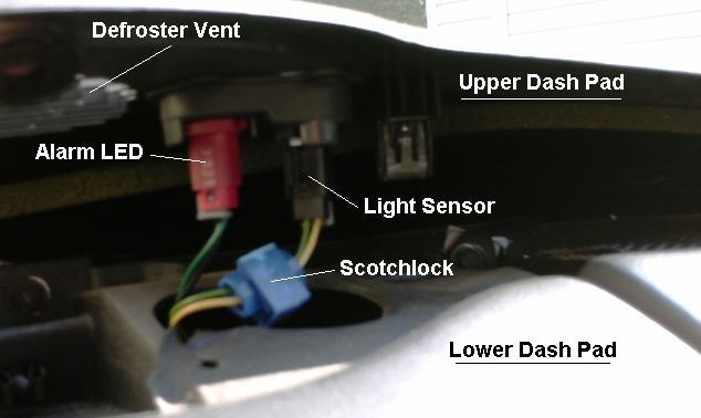
The light sensor for the feature is located near the alarm LED. Short together the two wires going to it. A Scotch Lock works well for this (3M calls it Scotchlok). That will make the system think its always daytime and never auto activate the headlights. If you want a less permanent defeat or want some control over when to defeat it, you can wire in a switch instead of just shorting them together.
The light sensor for the feature is located near the alarm LED. Short together the two wires going to it. A Scotch Lock works well for this (3M calls it Scotchlok). That will make the system think its always daytime and never auto activate the headlights. If you want a less permanent defeat or want some control over when to defeat it, you can wire in a switch instead of just shorting them together.
Originally Posted by WhiteBird00
Remove the t-tops. At the top of the windshield pillar trim, remove the two Phillips screws then remove the windshield pillar trim (it just snaps off after the screws are removed). Carefully pry up the edge of the upper dash panel. It is held in place by a combination of clips and velcro pads. You can see one of the clips in the photo just above the words "Light Sensor". BE CAREFUL! The edges of the panel are sharp (don't ask how I found that out, he says as he types with nine fingers ). Also, the plastic can get somewhat brittle with age so it's best to pry it up in small sections - don't just pry up the center and then try to lift the whole thing.
Once you get the dash panel pried up, you'll see the sensor just like in the photo VIP1 posted above. The whole job can be done in 10 minutes after you've done it the first time and know where all the clips are. Allow about half an hour for the first time.
Once you get the dash panel pried up, you'll see the sensor just like in the photo VIP1 posted above. The whole job can be done in 10 minutes after you've done it the first time and know where all the clips are. Allow about half an hour for the first time.
Last edited by VIP1; 04-29-2008 at 10:06 PM.
Trending Topics
11-15-2007, 02:53 PM
#8
Copy & Paste Moderator
Thread Starter
Fog Lights - Camaro
Hella Micro DE & Catz 5.5" Driving Lights
https://ls1tech.com/forums/appearance-detailing/480273-new-fog-lights-my-z-pics.html
Catz 5.5" Round Driving Lights Behind Grill
https://ls1tech.com/forums/appearance-detailing/353640-5-5-dia-driving-lights-behind-my-grille-pics.html
Large Round "1969 Style" Fog Lights Behind Grill
https://ls1tech.com/forums/appearance-detailing/468936-how-install-round-1969-style-foglights-grille.html
PIAA 1100x Platinum
https://ls1tech.com/forums/appearance-detailing/512329-piaa-s-installed.html
Hella Micro DE:
https://ls1tech.com/forums/showthread.php?t=480273
https://ls1tech.com/forums/appearanc...ns-update.html
Blazer Fog Lights:
https://ls1tech.com/forums/appearance-detailing/943767-added-projector-fogs-match.html
Last edited by VIP1; 07-09-2016 at 06:25 PM.
11-15-2007, 02:57 PM
#9
Copy & Paste Moderator
Thread Starter
Fog Lights - Firebird
Firebird/Formula
Cyber White (55w H3)
http://www.fadingarrow.com/foglights.htm
https://ls1tech.com/forums/appearanc...8-formula.html
http://www.fullthrottlev6.com/forums...in-98-Firebird
Hella 90mm projectors:
https://ls1tech.com/forums/appearance-detailing/1011563-swapped-my-fogs-set-projectors.html
https://ls1tech.com/forums/appearance-detailing/1095424-aftermarket-halo-install-around-projector-fog-lights-my-formula.html
2000-2002 Dodge Neon SRT-4 Fog Lights
(Uses the stock 880 bulb)
https://ls1tech.com/forums/appearanc...e-install.html
Morimoto Ford F150 LED Fog Light housings
https://ls1tech.com/forums/appearanc...-housings.html
Hella Micro DE
https://ls1tech.com/forums/appearanc...la-bumper.html
Trans AM
APC 70w Fog Light
https://ls1tech.com/forums/appearance-detailing/270640-apc-70w-fog-light-install-pics.html
(Several more links on page 2)
Hella Optilux 2500 Angel Eye
https://ls1tech.com/forums/stereo-el...t-upgrade.html
Hella 90mm H7 Fog Lights
https://ls1tech.com/forums/appearanc...ll-w-pics.html
Hella 90mm Projectors
https://ls1tech.com/forums/appearanc...rojectors.html
https://ls1tech.com/forums/appearanc...y-formula.html
https://ls1tech.com/forums/appearanc...onversion.html
Pilot Navigator NV-362W
https://ls1tech.com/forums/pontiac-f...og-lights.html
LED Fog Light Housings (similar to Morimoto)
https://ls1tech.com/forums/appearanc...knockoffs.html
https://ls1tech.com/forums/appearanc...g-upgrade.html
Last edited by VIP1; 03-17-2020 at 11:03 AM.
01-17-2008, 09:30 PM
#10
Copy & Paste Moderator
Thread Starter
Monsoon headunit Display and Button Lights issues
Here is a thread on how Midnight F-117A replaced the blown bulbs in his Monsoon headunit with LEDs:
https://ls1tech.com/forums/wiring-stereo-electronics/113734-ya-think-i-m-gonna-buy-head-unit-when-i-did.html
Here is another link on replacing the bulbs with LEDs:
http://xse.com/leres/ss/leds.html
Here are some threads about Monsoon Display issues:
https://ls1tech.com/forums/showthrea...onsoon+display
https://ls1tech.com/forums/showthrea...onsoon+display
https://ls1tech.com/forums/showthrea...onsoon+display
https://ls1tech.com/forums/showthrea...onsoon+display
https://ls1tech.com/forums/showthrea...onsoon+display
https://ls1tech.com/forums/stereo-el...n-display.html
https://ls1tech.com/forums/showthrea...onsoon+display
Replacing the display bulb: (AC Delco #16208443)
http://www.fiero.nl/forum/Forum1/HTML/089227.html
Last edited by wssix99; 01-26-2016 at 09:55 AM. Reason: Added the Display Bulb link
03-05-2008, 11:38 AM
#11
Copy & Paste Moderator
Thread Starter
Firebird Headlight Noise Or Odd Behavior
Here is the TransAm Headlight Sticky:
https://ls1tech.com/forums/pontiac-firebird-1967-2002/177470-firebird-headlights-all-comments-questions-regarding-headlights-go-here.html
Contains info on symptoms, the free 180* fix, brass gears, and a video.
Here is a post about cheaper plastic replacement gears:
https://ls1tech.com/forums/showpost....4&postcount=10
09-25-2009, 09:03 AM
#12
Copy & Paste Moderator
Thread Starter
Firebird Fixed-Headlight Conversions (No-Popups)
https://ls1tech.com/forums/appearance-detailing/457545-car-update-2-21-06-pics-56k-ehhh-how-bout-no.html
https://ls1tech.com/forums/showthread.php?t=615280
https://ls1tech.com/forums/appearance-detailing/520973-i-said-i-d-do-if-no-one-else-did-here-they-fixed-ta-headlights.html
https://ls1tech.com/forums/pontiac-firebird-1967-2002/281936-fixed-ta-headlights-coming-thread-feb-2005-a.html
https://ls1tech.com/forums/appearance-detailing/280494-working-producing-non-pop-up-head-lights-ta.html
https://ls1tech.com/forums/appearance-detailing/245318-head-lights.html
https://ls1tech.com/forums/appearance-detailing/237552-fixed-ta-headlights.html
https://ls1tech.com/forums/appearance-detailing/157906-non-pop-up-headlight-gp-corvettes-firebirds.html
https://ls1tech.com/forums/new-ls1-owners-newbie-tech/150324-ta-fixed-headlights.html
https://ls1tech.com/forums/appearance-detailing/14137-trans-am-headlight-conversion-clear-covers.html
https://ls1tech.com/forums/appearance-detailing/14073-ta-fixed-headlights.html
https://ls1tech.com/forums/appearance-detailing/128570-fixed-headlights-t-s.html
Last edited by VIP1; 11-10-2011 at 09:25 AM.