

Invading Germany: LSX into BMW E34 525/535

While looking over the motor as it sat on the stand today, I realized there was no need to redo the passenger frame rail motor mount. Since the GTO/C5 mounts bolt onto the block where it is angled, I have been looking at this as the area to attach motor mounts. I found the AC bracket has three nice 10mm threaded holes in the block right at the front. Since the GTO bracket attaches with 3 x 10mm bolts, this should provide a similar strength.
What I can now do is get a piece of oversize angle iron and mount the OEM BMW rubber mount on it at 90 degrees to the bottom of the block. Dimensionally, it will need to be 6" long, up to 4" high, and 6" out. I can reinforce the corners as needed with more metal. Online Metal sells a .3125" thick piece that is 4x6, and they even cut it to length (this is where I got my motor mount relocation plates I used on the driver side). The AC bracket can fit on top of this. With .3125 spacers at the top and a longer 4 rib belt I should be in business.
AC
I got my GM service manual loaded up & looked up the 1998 C5 and F-body AC schematics as well as the one from the BMW. The BMW system is very complex, but it boils down to a lot of extra wiring & relays to control the auxiliary fan. Here is a wiring comparison of both systems, based on the shop manuals (high resolution, click here).
Here is that forest & tree thing again. The F-bodies are wired for two fans, one of which is really a supplemental fan. I had it in my head my MK8 fan was a single speed and that is how I should wire the car. DING! The car has two fans, just like an F-body, so I can wire the MK8 as fan 1 and set the on/off temps via HP Tuners, and use the condenser fan as fan 2.
I will retain the BMW compressor relay so I can use the existing wiring at the DME harness to connect to the PCM. I will need to add a GM pressure sensor since I could not get exact values to compare to the BMW unit.
Wiring
Speaking of wiring, I updated the diagram with the above info, as well as moving the fuel pump relay back into the car (it will locate in the back seat area near the battery). Since the diagram is hard to read at lower resolutions like the pics I post in these threads, I am providing a link to it on my Photobucket page.
What I can now do is get a piece of oversize angle iron and mount the OEM BMW rubber mount on it at 90 degrees to the bottom of the block. Dimensionally, it will need to be 6" long, up to 4" high, and 6" out. I can reinforce the corners as needed with more metal. Online Metal sells a .3125" thick piece that is 4x6, and they even cut it to length (this is where I got my motor mount relocation plates I used on the driver side). The AC bracket can fit on top of this. With .3125 spacers at the top and a longer 4 rib belt I should be in business.
AC
I got my GM service manual loaded up & looked up the 1998 C5 and F-body AC schematics as well as the one from the BMW. The BMW system is very complex, but it boils down to a lot of extra wiring & relays to control the auxiliary fan. Here is a wiring comparison of both systems, based on the shop manuals (high resolution, click here).
Here is that forest & tree thing again. The F-bodies are wired for two fans, one of which is really a supplemental fan. I had it in my head my MK8 fan was a single speed and that is how I should wire the car.
I will retain the BMW compressor relay so I can use the existing wiring at the DME harness to connect to the PCM. I will need to add a GM pressure sensor since I could not get exact values to compare to the BMW unit.
Wiring
Speaking of wiring, I updated the diagram with the above info, as well as moving the fuel pump relay back into the car (it will locate in the back seat area near the battery). Since the diagram is hard to read at lower resolutions like the pics I post in these threads, I am providing a link to it on my Photobucket page.

I'm batting 0 for 3 for AC on these swaps for various reasons, and I want this one to be done correctly so other family members will ride in my wagon
 .
.BTW just sold the motor from the BMW to a friend of TwistedSS, both super nice guys who drove all day to get here. It would be great to be able to handle all transactions like this.
Audio
I spent the past couple of days pulling trim & running wire & cable for a remote amp and component speaker setup. I also had to fabricate aluminum brackets for the 1" tweeters to fit into the BMW dash and rear ceiling openings. I am running a 70Wx4 channel amp in the left rear under the trim panel, and replaced the OEM speakers with 5.25" Infinity components.
This is the original rear ceiling setup:

Here are the Infinity woofer & tweeter:

EDIT- I used JB Weld here also & reattached the tab that had broken off. This stuff is so good I may just use it to mount the motor instead of waiting for the new angle iron .
.
Seems like I routed about 100 wires back here:

Amp installed on 11-2-07:

Here is the dash w/o the radio but with the install sleeve:

Here is the Sony installed:

Fuel
Follow up parts are trickling in. I got the -5 to -6 male adapter so I could hook up the rest of the fuel line to the FPR.
The TRE-340 fuel pump came today:

Missing from the pic & the box was the fuel strainer. The company was good about it & is sending another strainer, albeit by regular postal mail* from across the country.
Rant
This was their screwup/shortage and the part should have been overnighted. It's not like I have the pump apart & need this ASAP- wait a minute, I do!
UPDATED RANT 11-7-07
I find it incredible that when a company is notified of a problem they fail to address it in a timely manner, and act like it is your fault. Since I still had not received the strainer as of 11-7-07, 11 days after I paid for the pump and 5 days after I had been advised it had been mailed, I followed up with TRE:
I'm really let down by this transaction since as of today's mail I still do not have a strainer. The Post Office says it should that 3 mailing days to go 1st Class Mail from your ZIP to mine, and I allowed an extra day since I am in a rural area.
Since the omission of the strainer from the box was not my fault, I think it would be a better business practice in a situation like this to expedite delivery of the shorted part/parts. I am not a random customer, this is the third pump I have purchased from your company for the seven vehicles I own.
I am offering this information so that you may evaluate the situation so as to prevent it from reoccurring. I am fortunate that this is for a project, so the delay is only irritating. Were this for a daily driven vehicle, it would cause a significant problem for me.
Here is the email response I got today:
The strainer came back like 16 cents too short and went out again
tuesday. These ALWAYS include the parts and are hand packed, so it is
highly unlikely but maybe it wasn't noticed...but I just sent you one
anyways. You will see that on the envelope. We did not ask for money
or proof and just sent the strainer. Most would require all parts to be
sent back, so I would think that is acceptable. I don't know what else
you could have wanted other than the service you got.
Here is my reply:
All I wanted was a complete fuel pump kit as described on your website, which was what I paid for. The pump came Priority Mail, so why couldn't the part that was supposed to be with the pump? Ask me for money? Why? I already paid for it. You want proof? I have a 7+ page build thread on this car that is updated daily and I photograph the work I am doing, which includes the parts I receive. Here is your proof (see post #123 on this page):
https://ls1tech.com/forums/showthrea...=768900&page=7
Check my trader rating on LS1tech- I don't rip people off even when others have ripped me off. Think about this- if I was out to scam you, why would I buy two pumps w/o any issue and then try & pull a fast one on the third?
Now you are telling me there is another delay and I won't have the part until the weekend. I'd love to send it back to you, but I need to get this part of the project done seeing as how the pump has been out of the car since October 26 when I ordered your pump. That was 11 days ago and I have already wired/plumbed the car's pump wiring/fittings for use of this pump.
Thanks for the reply. I'll pass this information along on my build threads and will shop elsewhere for any future needs.
BASED ON THIS INFORMATION, I WILL NOT DO BUSINESS WITH TRE PERFORMANCE AGAIN.
/Rant
Gauges
I also got the plastic box that I am planning to mount the 2&5/8" gauges into:


It would actually fit better upside down due to the slope of the dash, but all things considered it is not too bad. If I did that, the metal bottom panel would show and it would not look so good. I hope there is enough room for the gauges to fit in since the top slopes back.
UPDATE 11-1-07
Clutch pedal
It turns out the parts in the online parts listing for the return spring don't fit my car. Fortunately, the pedal assembly I bought had a return spring for the brake pedal I was able to use. The book shows a spring on the end of the master cylinder, versus the brake pedal setup that coils around the pivot shaft of the pedal. The bracket had holes for this type of spring, so I'm sure that was the type that was supposed to be used. Bottom line is the pedal goes down & comes back up.
Wiring
My Waytek Wiring order came today, so I did some work in that area:
Fuel pump
I ran a 12 gauge wire from the rear seat (battery) area under the car and cut the green/violet wire at the tank fitting and spliced the 12 gauge wire there.

I added a relay bracket in the rear seat area along with an inline fuse. All I need to do now is to run a small gauge green wire from the PCM area under the hood back to here & this circuit is complete. With this setup, I can also run a boost-a-pump if needed.

I found that the TRE fuel pump wiring used the same terminals to attach to the pump as the ones I got from Waytek for the relay plugs. I cut the wires off at the ring terminals for the BMW fuel pump and crimp/soldered two of these connectors on. After removing the wires from the TRE plug, I was able to slip these in & it is a great fit. I also drilled a hole in the center of the BMW pump holder since the TRE-340 has a center outlet vs. the offset BMW outlet. I may need to lower the pump depending on how the strainer sits (once it gets here).

Relay panel
To operate the fans, power the add-on fuse panel, and adapt the low oil level sensor requires 5 relays. I have a diagram of what is planned here:

Here is the actual relay part of this layout:

This fits in the passenger side E-box where the BMW engine control computer was. I have to run supply & output wires in and out of the box, but the relay panel is a good fit.
The relay brackets allow for use of a 4 or 5 terminal relay, and have mounting tabs. I used a 1" strip of .125" aluminum to mount them. The 1/4-20 bolts are like 1/2" long and the nuts & lock washers allow it to be wedged in place perfectly. This way I can replace the relays very easily. The fans will each use a Tyco relay rated at 50 amps, the #3 fan, fuse box, and oil level will use a 30A version. The #3 fan and oil level relays are 5 terminal, the rest are 4. I'm going to run 8 gauge wire to the Mark 8 fan and 10 gauge to the BMW fan. Although the MK 8 is a larger fan, it seems to draw less current than the Taurus fan in my RX7 (based on the ones in my 280Z & Supra). I like to over wire on something critical like this.
Here is the finished setup. Everything fits inside the E-box!:

Included in my order were some Maxi fuse holders. These things run 6 gauge wire & can carry big current. I'm using one under the seat for the amp & a second one for the MK 8 fan. I also got some trick 30A waterproof fuse holders with 12 gauge wires for like $2.50 each.
Clutch
I completed the remote bleeder setup with the -4 hose & fittings. Still waiting on the 90 degree -3 fitting for the funky town master cylinder and then this plumbing will be good to go.

I spent the past couple of days pulling trim & running wire & cable for a remote amp and component speaker setup. I also had to fabricate aluminum brackets for the 1" tweeters to fit into the BMW dash and rear ceiling openings. I am running a 70Wx4 channel amp in the left rear under the trim panel, and replaced the OEM speakers with 5.25" Infinity components.
This is the original rear ceiling setup:
Here are the Infinity woofer & tweeter:
EDIT- I used JB Weld here also & reattached the tab that had broken off. This stuff is so good I may just use it to mount the motor instead of waiting for the new angle iron
.Seems like I routed about 100 wires back here:
Amp installed on 11-2-07:
Here is the dash w/o the radio but with the install sleeve:
Here is the Sony installed:
Fuel
Follow up parts are trickling in. I got the -5 to -6 male adapter so I could hook up the rest of the fuel line to the FPR.
The TRE-340 fuel pump came today:
Missing from the pic & the box was the fuel strainer. The company was good about it & is sending another strainer, albeit by regular postal mail* from across the country.
Rant
This was their screwup/shortage and the part should have been overnighted. It's not like I have the pump apart & need this ASAP- wait a minute, I do!
UPDATED RANT 11-7-07
I find it incredible that when a company is notified of a problem they fail to address it in a timely manner, and act like it is your fault. Since I still had not received the strainer as of 11-7-07, 11 days after I paid for the pump and 5 days after I had been advised it had been mailed, I followed up with TRE:
I'm really let down by this transaction since as of today's mail I still do not have a strainer. The Post Office says it should that 3 mailing days to go 1st Class Mail from your ZIP to mine, and I allowed an extra day since I am in a rural area.
Since the omission of the strainer from the box was not my fault, I think it would be a better business practice in a situation like this to expedite delivery of the shorted part/parts. I am not a random customer, this is the third pump I have purchased from your company for the seven vehicles I own.
I am offering this information so that you may evaluate the situation so as to prevent it from reoccurring. I am fortunate that this is for a project, so the delay is only irritating. Were this for a daily driven vehicle, it would cause a significant problem for me.
Here is the email response I got today:
The strainer came back like 16 cents too short and went out again
tuesday. These ALWAYS include the parts and are hand packed, so it is
highly unlikely but maybe it wasn't noticed...but I just sent you one
anyways. You will see that on the envelope. We did not ask for money
or proof and just sent the strainer. Most would require all parts to be
sent back, so I would think that is acceptable. I don't know what else
you could have wanted other than the service you got.
Here is my reply:
All I wanted was a complete fuel pump kit as described on your website, which was what I paid for. The pump came Priority Mail, so why couldn't the part that was supposed to be with the pump? Ask me for money? Why? I already paid for it. You want proof? I have a 7+ page build thread on this car that is updated daily and I photograph the work I am doing, which includes the parts I receive. Here is your proof (see post #123 on this page):
https://ls1tech.com/forums/showthrea...=768900&page=7
Check my trader rating on LS1tech- I don't rip people off even when others have ripped me off. Think about this- if I was out to scam you, why would I buy two pumps w/o any issue and then try & pull a fast one on the third?
Now you are telling me there is another delay and I won't have the part until the weekend. I'd love to send it back to you, but I need to get this part of the project done seeing as how the pump has been out of the car since October 26 when I ordered your pump. That was 11 days ago and I have already wired/plumbed the car's pump wiring/fittings for use of this pump.
Thanks for the reply. I'll pass this information along on my build threads and will shop elsewhere for any future needs.
BASED ON THIS INFORMATION, I WILL NOT DO BUSINESS WITH TRE PERFORMANCE AGAIN.
/Rant
Gauges
I also got the plastic box that I am planning to mount the 2&5/8" gauges into:
It would actually fit better upside down due to the slope of the dash, but all things considered it is not too bad. If I did that, the metal bottom panel would show and it would not look so good. I hope there is enough room for the gauges to fit in since the top slopes back.
UPDATE 11-1-07
Clutch pedal
It turns out the parts in the online parts listing for the return spring don't fit my car. Fortunately, the pedal assembly I bought had a return spring for the brake pedal I was able to use. The book shows a spring on the end of the master cylinder, versus the brake pedal setup that coils around the pivot shaft of the pedal. The bracket had holes for this type of spring, so I'm sure that was the type that was supposed to be used. Bottom line is the pedal goes down & comes back up.
Wiring
My Waytek Wiring order came today, so I did some work in that area:
Fuel pump
I ran a 12 gauge wire from the rear seat (battery) area under the car and cut the green/violet wire at the tank fitting and spliced the 12 gauge wire there.
I added a relay bracket in the rear seat area along with an inline fuse. All I need to do now is to run a small gauge green wire from the PCM area under the hood back to here & this circuit is complete. With this setup, I can also run a boost-a-pump if needed.
I found that the TRE fuel pump wiring used the same terminals to attach to the pump as the ones I got from Waytek for the relay plugs. I cut the wires off at the ring terminals for the BMW fuel pump and crimp/soldered two of these connectors on. After removing the wires from the TRE plug, I was able to slip these in & it is a great fit. I also drilled a hole in the center of the BMW pump holder since the TRE-340 has a center outlet vs. the offset BMW outlet. I may need to lower the pump depending on how the strainer sits (once it gets here).
Relay panel
To operate the fans, power the add-on fuse panel, and adapt the low oil level sensor requires 5 relays. I have a diagram of what is planned here:
Here is the actual relay part of this layout:
This fits in the passenger side E-box where the BMW engine control computer was. I have to run supply & output wires in and out of the box, but the relay panel is a good fit.
The relay brackets allow for use of a 4 or 5 terminal relay, and have mounting tabs. I used a 1" strip of .125" aluminum to mount them. The 1/4-20 bolts are like 1/2" long and the nuts & lock washers allow it to be wedged in place perfectly. This way I can replace the relays very easily. The fans will each use a Tyco relay rated at 50 amps, the #3 fan, fuse box, and oil level will use a 30A version. The #3 fan and oil level relays are 5 terminal, the rest are 4. I'm going to run 8 gauge wire to the Mark 8 fan and 10 gauge to the BMW fan. Although the MK 8 is a larger fan, it seems to draw less current than the Taurus fan in my RX7 (based on the ones in my 280Z & Supra). I like to over wire on something critical like this.
Here is the finished setup. Everything fits inside the E-box!:
Included in my order were some Maxi fuse holders. These things run 6 gauge wire & can carry big current. I'm using one under the seat for the amp & a second one for the MK 8 fan. I also got some trick 30A waterproof fuse holders with 12 gauge wires for like $2.50 each.
Clutch
I completed the remote bleeder setup with the -4 hose & fittings. Still waiting on the 90 degree -3 fitting for the funky town master cylinder and then this plumbing will be good to go.
Last edited by V8 Supra Builder; Nov 7, 2007 at 08:28 PM. Reason: Why I won't buy another TRE fuel pump!
It seems like every aspect of this project has been torpedoed in one aspect or another by parts suppliers, whether it be the crook with the junk heads, the wrong fittings for the remote bleeder, or the missing fuel pump strainer. Even the amp was out of stock from the place I bought the speakers (yes, they showed it in stock when I ordered, at least they notified me they were out within a day).
Anyhow, the banjo PS fittings arrived today so I was able to cut the PS pressure hose from the Hydroboost to the steering box, and put the banjo fittings in place on the pump.
The stereo upgrade was finished today. It is great to actually have one thing completed, even though it has nothing to do with the swap.
I picked up a damaged (the C210-220-230 inside the car connectors had been cut off, the EGR plug had a cut wire, and the oil level sensor plug was gone) 1998 LS1 F-body harness from a JY for $50.

The nice thing about damaged harnesses is the price. The not so nice thing is identifying wires & making repairs. I spent most of the evening with my service manual, diagrams, an ohm meter, and my handy label printer. I have the ones from my wiring diagram identified so I can start work on this part of things tomorrow. Fortunately the parts that were cut off or damaged (except for the oil level plug) would have been cut off by me anyway.
My wiring will use GXL wire which is rated for under hood automotive use. I'm also crimping & soldering all connectors where possible. I have learned the hard way that cheap wire (i.e. Advanced Auto Parts et al) will let you down at some point, that point usually being 20 miles outside of town. No big surprise that there is a one week lead time before the vendor can ship.
My metal order for the passenger motor mount bracket is still in process. Once this gets here along with the C5 bracket & compressor and the H3 oil pan I will be able to make some good progress and get the motor & trans in. Then all I have to worry about is fitting the exhaust & turbo.
Anyhow, the banjo PS fittings arrived today so I was able to cut the PS pressure hose from the Hydroboost to the steering box, and put the banjo fittings in place on the pump.
The stereo upgrade was finished today. It is great to actually have one thing completed, even though it has nothing to do with the swap.
I picked up a damaged (the C210-220-230 inside the car connectors had been cut off, the EGR plug had a cut wire, and the oil level sensor plug was gone) 1998 LS1 F-body harness from a JY for $50.
The nice thing about damaged harnesses is the price. The not so nice thing is identifying wires & making repairs. I spent most of the evening with my service manual, diagrams, an ohm meter, and my handy label printer. I have the ones from my wiring diagram identified so I can start work on this part of things tomorrow. Fortunately the parts that were cut off or damaged (except for the oil level plug) would have been cut off by me anyway.
My wiring will use GXL wire which is rated for under hood automotive use. I'm also crimping & soldering all connectors where possible. I have learned the hard way that cheap wire (i.e. Advanced Auto Parts et al) will let you down at some point, that point usually being 20 miles outside of town. No big surprise that there is a one week lead time before the vendor can ship.
My metal order for the passenger motor mount bracket is still in process. Once this gets here along with the C5 bracket & compressor and the H3 oil pan I will be able to make some good progress and get the motor & trans in. Then all I have to worry about is fitting the exhaust & turbo.
I was having spaghetti for breakfast, lunch, and dinner today :

The bundle in the upper right is from the BMW DME, and most of these will be removed once I get the ones I need to use selected. I have to keep them connected for now so I can ID them by number/position on the connector.
The PCM & bracket were a real tight squeeze in the cowl behind the passenger E-box. I took an F-body PCM bracket and cut the support, heated it and flattened the support (the whole bracket is plastic). This allowed it to mate up with yet another fabricated aluminum bracket that tied in to an existing screw and I drilled a hole in the inner fender for the other end. I had to remove the E-box to get the wiring connectors in place.

I cut the grommet on the side of the E-box where the BMW wiring goes through and passed the PCM connectors and plugs C100, 101, and 105 through. The other C series plugs that usually go inside the cab (210-220-230) were cut off, so I will only pass through the wires I need from them. I found that the fuel pump relay is located in the E-box, and the power feed wire goes from here to a 15A fuse and then back to the pump via the backseat! Translation: No need to run another wire back to there, a major time saver. The wire is larger than the others and is green/violet stripe. I tested continuity before cutting, and this is the one I needed. On the back seat area, it passes through the floor behind the battery with several other wires, but it is the only green/violet one. I snipped it at both ends and attached it to the PCM fuel pump relay wire in the E-box & the new relay under the back seat. Fuel pump relay wiring complete .
.
I was able to use up some leftover wire from prior projects as well as from my truck harnesses for the relay trigger circuits and short power feeds. It looks like all of this will fit inside the E-box OK.
I revised the overall wiring diagram again & realized I will have to update it as I go due to unforeseen items such as the microscopic ground lead on the BMW DME. I figured it was better to run my own heavier wire here.
Here is a link to my latest (11-04-07) wiring version (prior ones were deleted for clarity) :
http://i243.photobucket.com/albums/f...07largeJPG.jpg
I can't finish this part due to the lead time on the wiring order for the 8 and 10 gauge wires as well as the wiring into the cab, although I may cut into my old truck harnesses if there is a long enough piece there. I found a pass through in the firewall behind the E-box while it was out.
This is one of the most tedious parts of the swap, but it pays to do it right the first time so everything works when you hook up the battery.
Mentioned earlier in the thread was the ability to use tuning software to adjust the tach output. I did some research on this, and here is what I found:
The default setting on HP Tuners for "Tach Resolution" is 6/6. This is for the LSx motors, which regular tachs read as a 4 cylinder. Without going into all the details, here are the relevant swap settings:
Older V8: 3/3
6 cylinder: 4/4
4 cylinder: 6/6 (apparently also correct for rotary motors)
If this turns out to be wrong after I get everything done, I will update here.
I'd like to give a thumbs up to fellow BMW builder Thaniel here. He PM'd me offering his oil level plug & sensor since his setup did not require them. Every $ saved works for me. I hate to throw out parts, but sometimes it has to be done:

Garage clearing prior to moving: Wrecked '91 Supra parts car w/ two Supra motors, one Supra auto trans, one RX7 motor & trans, plus a bunch of interior parts headed to the junkyard!
At least they weren't Chevy parts!
:The bundle in the upper right is from the BMW DME, and most of these will be removed once I get the ones I need to use selected. I have to keep them connected for now so I can ID them by number/position on the connector.
The PCM & bracket were a real tight squeeze in the cowl behind the passenger E-box. I took an F-body PCM bracket and cut the support, heated it and flattened the support (the whole bracket is plastic). This allowed it to mate up with yet another fabricated aluminum bracket that tied in to an existing screw and I drilled a hole in the inner fender for the other end. I had to remove the E-box to get the wiring connectors in place.
I cut the grommet on the side of the E-box where the BMW wiring goes through and passed the PCM connectors and plugs C100, 101, and 105 through. The other C series plugs that usually go inside the cab (210-220-230) were cut off, so I will only pass through the wires I need from them. I found that the fuel pump relay is located in the E-box, and the power feed wire goes from here to a 15A fuse and then back to the pump via the backseat! Translation: No need to run another wire back to there, a major time saver. The wire is larger than the others and is green/violet stripe. I tested continuity before cutting, and this is the one I needed. On the back seat area, it passes through the floor behind the battery with several other wires, but it is the only green/violet one. I snipped it at both ends and attached it to the PCM fuel pump relay wire in the E-box & the new relay under the back seat. Fuel pump relay wiring complete
.I was able to use up some leftover wire from prior projects as well as from my truck harnesses for the relay trigger circuits and short power feeds. It looks like all of this will fit inside the E-box OK.
I revised the overall wiring diagram again & realized I will have to update it as I go due to unforeseen items such as the microscopic ground lead on the BMW DME. I figured it was better to run my own heavier wire here.
Here is a link to my latest (11-04-07) wiring version (prior ones were deleted for clarity) :
http://i243.photobucket.com/albums/f...07largeJPG.jpg
I can't finish this part due to the lead time on the wiring order for the 8 and 10 gauge wires as well as the wiring into the cab, although I may cut into my old truck harnesses if there is a long enough piece there. I found a pass through in the firewall behind the E-box while it was out.
This is one of the most tedious parts of the swap, but it pays to do it right the first time so everything works when you hook up the battery.
Mentioned earlier in the thread was the ability to use tuning software to adjust the tach output. I did some research on this, and here is what I found:
The default setting on HP Tuners for "Tach Resolution" is 6/6. This is for the LSx motors, which regular tachs read as a 4 cylinder. Without going into all the details, here are the relevant swap settings:
Older V8: 3/3
6 cylinder: 4/4
4 cylinder: 6/6 (apparently also correct for rotary motors)
If this turns out to be wrong after I get everything done, I will update here.
I'd like to give a thumbs up
Garage clearing prior to moving: Wrecked '91 Supra parts car w/ two Supra motors, one Supra auto trans, one RX7 motor & trans, plus a bunch of interior parts headed to the junkyard!
At least they weren't Chevy parts!
Last edited by V8 Supra Builder; Nov 5, 2007 at 01:07 AM. Reason: Cleaning up the thread, deleting useless info
Glad to see you are progressing. Sucks to throw away parts but sometimes you have to do it. I had to move last year after I sold my car and could not get rid of some extra parts. I ended up junking them which sucked because I knew someone somewhere would have had use for them....oh well.
I went through pages 1-7 this morning & deleted a bunch of useless info & pics.
Still in a basic holding pattern until the oil pan & wiring stuff gets here.
I did test the stereo last night & it sounds good. Unfortunately it has blue lighting, but the price was right on it. Surprisingly, the dash did not freak out as I had expected. I got low oil, foglight, and trans program errors (maybe a couple more, I was working on the stereo at the time). I need to find the trans control module (it's not where the manual says it should be ) so I can ground one wire & take care of this problem.
The overall wiring diagram has been updated as I sort through stuff. I found & tested the backup wires for the T56 & BMW and this is now on the latest diagram, as are the C-series connector pinouts to the DME or other locations.
Still in a basic holding pattern until the oil pan & wiring stuff gets here.
I did test the stereo last night & it sounds good. Unfortunately it has blue lighting, but the price was right on it. Surprisingly, the dash did not freak out as I had expected. I got low oil, foglight, and trans program errors (maybe a couple more, I was working on the stereo at the time). I need to find the trans control module (it's not where the manual says it should be
The overall wiring diagram has been updated as I sort through stuff. I found & tested the backup wires for the T56 & BMW and this is now on the latest diagram, as are the C-series connector pinouts to the DME or other locations.
As I wait for more parts, I am completing some small tasks.
Backup lights
Last night I identified the wires needed to operate the backup lights. There is a connector in front of the shifter that has 7 wires going to it. It was connected to the "Transmission Range Switch" that is on the auto shifter. The wires of interest here were the Blue/Yellow one that goes to the backup lamps and a Green/Black one that provides power for the lamps. The corresponding wires on the 1998 F-body harness are located on connector C230. The light green wire at pin J goes to the lamps, and the brown wire at pin G connects to the power. I tested the BMW wire by putting +12V to it & the lamps came on. Here is a pic of the Weather Pack connector in place:

Low brake fluid sensor
Since I am using a cobra Hydroboost, it has the Cobra MC. This unit uses a 3 wire plug, whereas the BMW used a 2 wire plug. Gen3Benz is an official Alldata buddy and sent me the 97 Cobra diagram. It turns out both units turn on the dash lamp on low fluid by grounding the lamp. The extra wire on the Cobra activates some other stuff. Since I don't have my Motorcraft pigtail for this yet, all I could do at this point was to cut off the BMW plug & wire in a 2 terminal Weather Pack connector. I will do the same with the pigtail when it gets here.

BMW condenser fan wiring
While looking for the evasive trans control module, I found a relay box on the driver fender that controls the BMW condenser fan. I tested it and found the blue wire from the high speed relay (rearmost relay) runs the fan at full speed. I pulled the relay & put a spade connector in place. Once my 10 gauge wires get here, I can create a circuit to the fan without having to cut the fan wire.

Oil Cooler
I am using another B&M Supercooler. I have one of these on my Corvair and on my TA. Its area is about the size of a sheet of paper and it seems to work well. The inlets are 1/2" pipe. I'm running -10 hose to it. The circuit will start with a cooler adapter and thermostat under the oil filter mount on the pan. Once the oil gets hot enough, it will divert to the cooler and then return to the motor. I mounted the cooler in front of the condenser fan with three aluminum brackets and enlarged an existing hole for the fourth mounting point:

The oil cooler will have to share real estate with an intercooler. None of this would fit under the stock bumper, so I am planning to add a body kit bumper to the car. This one seems to have the most room of the ones I have looked at:

Pic courtesy Raceonusa if there is any question!
I have also started muffler measuring and shopping. I want to keep the stock appearance at the rear and use a 3" inlet. My Supra has a 3" in / dual 2.25" out made by Dynomax (PN 17740, 4.25" x 9.75" case) that I like, but the oval case is too wide to fit on the BMW. From the ones I have seen, I think I will end up with a round 7" unit. I found a Gibson muffler (758219) that is 3" in and dual 2.5" out. It has a 19" case and is 23" overall. It is rather expensive at about $140, but the sound clips for these sound very good- a little louder than stock. I can't handle Flowmaster type resonance in the cabin while driving. I looked at round Magnaflows, but the cases on the dual outlet ones are too long at 24". From my measurements, this would probably put the muffler in conflict with the rear tire. The stock muffler is curved for this reason. I need to recheck to see if I can fit a 5x8 case Magnaflow in there since these are available in a dual outlet also and are about $50 less than the Gibson.
My C5 compressor and high side line with sensor arrived today, no need for it as it was 46 degrees in the shop this morning. Once the bracket arrives, I will have another piece to the overall puzzle.
Backup lights
Last night I identified the wires needed to operate the backup lights. There is a connector in front of the shifter that has 7 wires going to it. It was connected to the "Transmission Range Switch" that is on the auto shifter. The wires of interest here were the Blue/Yellow one that goes to the backup lamps and a Green/Black one that provides power for the lamps. The corresponding wires on the 1998 F-body harness are located on connector C230. The light green wire at pin J goes to the lamps, and the brown wire at pin G connects to the power. I tested the BMW wire by putting +12V to it & the lamps came on. Here is a pic of the Weather Pack connector in place:
Low brake fluid sensor
Since I am using a cobra Hydroboost, it has the Cobra MC. This unit uses a 3 wire plug, whereas the BMW used a 2 wire plug. Gen3Benz is an official Alldata buddy and sent me the 97 Cobra diagram. It turns out both units turn on the dash lamp on low fluid by grounding the lamp. The extra wire on the Cobra activates some other stuff. Since I don't have my Motorcraft pigtail for this yet, all I could do at this point was to cut off the BMW plug & wire in a 2 terminal Weather Pack connector. I will do the same with the pigtail when it gets here.
BMW condenser fan wiring
While looking for the evasive trans control module, I found a relay box on the driver fender that controls the BMW condenser fan. I tested it and found the blue wire from the high speed relay (rearmost relay) runs the fan at full speed. I pulled the relay & put a spade connector in place. Once my 10 gauge wires get here, I can create a circuit to the fan without having to cut the fan wire.
Oil Cooler
I am using another B&M Supercooler. I have one of these on my Corvair and on my TA. Its area is about the size of a sheet of paper and it seems to work well. The inlets are 1/2" pipe. I'm running -10 hose to it. The circuit will start with a cooler adapter and thermostat under the oil filter mount on the pan. Once the oil gets hot enough, it will divert to the cooler and then return to the motor. I mounted the cooler in front of the condenser fan with three aluminum brackets and enlarged an existing hole for the fourth mounting point:
The oil cooler will have to share real estate with an intercooler. None of this would fit under the stock bumper, so I am planning to add a body kit bumper to the car. This one seems to have the most room of the ones I have looked at:
Pic courtesy Raceonusa if there is any question!
I have also started muffler measuring and shopping. I want to keep the stock appearance at the rear and use a 3" inlet. My Supra has a 3" in / dual 2.25" out made by Dynomax (PN 17740, 4.25" x 9.75" case) that I like, but the oval case is too wide to fit on the BMW. From the ones I have seen, I think I will end up with a round 7" unit. I found a Gibson muffler (758219) that is 3" in and dual 2.5" out. It has a 19" case and is 23" overall. It is rather expensive at about $140, but the sound clips for these sound very good- a little louder than stock. I can't handle Flowmaster type resonance in the cabin while driving. I looked at round Magnaflows, but the cases on the dual outlet ones are too long at 24". From my measurements, this would probably put the muffler in conflict with the rear tire. The stock muffler is curved for this reason. I need to recheck to see if I can fit a 5x8 case Magnaflow in there since these are available in a dual outlet also and are about $50 less than the Gibson.
My C5 compressor and high side line with sensor arrived today, no need for it as it was 46 degrees in the shop this morning. Once the bracket arrives, I will have another piece to the overall puzzle.
Wow, You are really steaming ahead on getting it done! Try the sound clip for the Edelbrock 55767 series -- 2 inlets & 2 outlets, case is about 3.62 x 9 x 19.
Garret & Steve
Almost done with E30-LS1 aka 357is
Garret & Steve
Almost done with E30-LS1 aka 357is

Thanks for the nice words from fellow BMW/RX-7 defilers . I need to stick with a 3" single inlet muffler as I don't want to run dual pipes under the car. Looks like the Magnaflow 5x8 case will fit so I will probably go that route.
Anyone that watched any movies involving Naval Aviation in the mid 80's (and probably some that were not even alive then) will recognize the exchange:
Maverick: "That's classified."
Charlie: "It's what?"
Maverick: "That's classified. I could tell you, but then I'd have to kill you."
This is how I was beginning to feel trying to find the lousy Transmission Control Module so I could ground pin #29 and get rid of the Trans Program message. The shop manual says it is in the E-box under the hood. Apparently the comrade that authored this portion's papers were not in order.
Fortunately, a couple of people came through on the BMW Forum & told me where BMW hid, er, put it. It is behind the passenger kick panel on the other side of the sheet metal.
Don't tell anyone.
Anyhow, with this major accomplishment under my belt, I pulled the passenger kick panel (I had this off a few days ago to put the Infinity speaker in here, would have been nice to know about it then). I found the bottom of the TCM & was able to get to the harness plug.

Here is where those doing this after me should be coughing up some royalties. I had to take the plug completely apart to find the Gray/Brown wire at pin 29. The connector is numbered, but you can't see what wire goes where unless it is apart.

Once this was done, I spliced into the Gray/Brown wire and grounded it to the kick panel metal.

A test showed I no longer have the Trans Program error displayed. I now only have the oil level sensor, coolant level sensor, and fog light messages. I also tested the brake fluid connector. With the wires shorted, I got the brake fluid message. With them apart, there was no message. When I bought the car, one of the glitches was the coolant level message. This would have needed fixing anyway.
In another parts frustration, Summit refunded all my money & did not send the exchange parts I wanted, so I had to re-order them today. They are quick shippers, so I should have this stuff by the end of the week.
Exhaust update
The 5x8 muffler will definitely fit, the old muffler seam to seam was over 8" wide. I test-fitted some leftover 3" tubing and a 45 degree bend. Looks like there is an odd angle coming from where the muffler will go towards where the pipe fits under the subframe, so I will probably look for some 15 or 30 degree bends to stay clear of the axle & subframe.
$30 3" Hedman offset pipe:

Give them a mask & a gun-
I thought it may be not too much more to pickup a 3" performance cat-back system for a 525. WRONG ANSWER! I found a place selling just a pipe & muffler for $755 .
.

Hey, and it was on sale- it WAS $800. What a rip. I can pickup the Magnaflow for $90 with free shipping, the bends (3) are at most $20 each, and 8' or so of tubing will add $25. Throw in another $100 for hangers, connectors, flanges, and electricity for welding it together and I'm looking at $275.
. I need to stick with a 3" single inlet muffler as I don't want to run dual pipes under the car. Looks like the Magnaflow 5x8 case will fit so I will probably go that route.Anyone that watched any movies involving Naval Aviation in the mid 80's (and probably some that were not even alive then) will recognize the exchange:
Maverick: "That's classified."
Charlie: "It's what?"
Maverick: "That's classified. I could tell you, but then I'd have to kill you."
This is how I was beginning to feel trying to find the lousy Transmission Control Module so I could ground pin #29 and get rid of the Trans Program message. The shop manual says it is in the E-box under the hood. Apparently the comrade that authored this portion's papers were not in order.
Fortunately, a couple of people came through on the BMW Forum & told me where BMW hid, er, put it. It is behind the passenger kick panel on the other side of the sheet metal.
Don't tell anyone.
Anyhow, with this major accomplishment under my belt, I pulled the passenger kick panel (I had this off a few days ago to put the Infinity speaker in here, would have been nice to know about it then). I found the bottom of the TCM & was able to get to the harness plug.
Here is where those doing this after me should be coughing up some royalties. I had to take the plug completely apart to find the Gray/Brown wire at pin 29. The connector is numbered, but you can't see what wire goes where unless it is apart.
Once this was done, I spliced into the Gray/Brown wire and grounded it to the kick panel metal.
A test showed I no longer have the Trans Program error displayed. I now only have the oil level sensor, coolant level sensor, and fog light messages. I also tested the brake fluid connector. With the wires shorted, I got the brake fluid message. With them apart, there was no message. When I bought the car, one of the glitches was the coolant level message. This would have needed fixing anyway.
In another parts frustration, Summit refunded all my money & did not send the exchange parts I wanted, so I had to re-order them today. They are quick shippers, so I should have this stuff by the end of the week.
Exhaust update
The 5x8 muffler will definitely fit, the old muffler seam to seam was over 8" wide. I test-fitted some leftover 3" tubing and a 45 degree bend. Looks like there is an odd angle coming from where the muffler will go towards where the pipe fits under the subframe, so I will probably look for some 15 or 30 degree bends to stay clear of the axle & subframe.
$30 3" Hedman offset pipe:
Give them a mask & a gun-
I thought it may be not too much more to pickup a 3" performance cat-back system for a 525. WRONG ANSWER! I found a place selling just a pipe & muffler for $755
Hey, and it was on sale- it WAS $800. What a rip. I can pickup the Magnaflow for $90 with free shipping, the bends (3) are at most $20 each, and 8' or so of tubing will add $25. Throw in another $100 for hangers, connectors, flanges, and electricity for welding it together and I'm looking at $275.
Last edited by V8 Supra Builder; Nov 6, 2007 at 04:55 PM.
I measured, marked, and cut the E-box cover so the wiring to the PCM could pass through and the box still be reasonably well covered:

I then slit & wrapped some 3/16 rubber hose around the opening to protect the wiring:

The cover fits in place fairly well:


Next up was evac of the AC system. Once this was done, I removed the condenser & compressor. I decided to replace the condenser since it had a pretty good gouge in it from the BMW motor hitting it on the way out (picture it dragging it's nails- "I don't want to go!!!!") .I found a good deal on an new 540 radiator & condenser, and am getting a coolant level sensor as well so this should take care of another dash message.
The condenser uses regular #6 & #8 female o-ring fittings. Since I'm using the C5 compressor, I needed an adapter block to use the same type of fittings. I got fittings from a Hot Rod Shop called Doc's Blocks. They have a good selection of many AC fittings/parts and decent prices.
The stumbling block here (isn't there always at least one?) is the evaporator AC fitting:


The tubes that ran into it were regular steel lines w/ o-rings, but they are held in place by a steel plate. I asked Doc's for help in adapting this, I suppose worst case I could cut the steel line, remove the plate, and transfer it to some aluminum lines of the proper size & then braze fittings onto them. I can't braze steel AC lines.
My fuel pump strainer should be with the mail today, if so, I can finally put the pump in place & get the tank closed up. My metal for the motor mount & Summit orders will be here tomorrow & Friday respectively, so as usual lots to do on the weekend. A little more wiring supplies, an oil pan, & some exhaust parts & I may be able to see some light at the end of the tunnel.
I then slit & wrapped some 3/16 rubber hose around the opening to protect the wiring:
The cover fits in place fairly well:
Next up was evac of the AC system. Once this was done, I removed the condenser & compressor. I decided to replace the condenser since it had a pretty good gouge in it from the BMW motor hitting it on the way out (picture it dragging it's nails- "I don't want to go!!!!") .I found a good deal on an new 540 radiator & condenser, and am getting a coolant level sensor as well so this should take care of another dash message.
The condenser uses regular #6 & #8 female o-ring fittings. Since I'm using the C5 compressor, I needed an adapter block to use the same type of fittings. I got fittings from a Hot Rod Shop called Doc's Blocks. They have a good selection of many AC fittings/parts and decent prices.
The stumbling block here (isn't there always at least one?) is the evaporator AC fitting:
The tubes that ran into it were regular steel lines w/ o-rings, but they are held in place by a steel plate. I asked Doc's for help in adapting this, I suppose worst case I could cut the steel line, remove the plate, and transfer it to some aluminum lines of the proper size & then braze fittings onto them. I can't braze steel AC lines.
My fuel pump strainer should be with the mail today, if so, I can finally put the pump in place & get the tank closed up. My metal for the motor mount & Summit orders will be here tomorrow & Friday respectively, so as usual lots to do on the weekend. A little more wiring supplies, an oil pan, & some exhaust parts & I may be able to see some light at the end of the tunnel.
The strainer did not come today.
On a happier note, I got the Motorcraft wiring pigtail (via UPS) for the Hydroboost MC, a used throttle body, and some metal wheel centering rings today- the plastic ones that were on the car were in poor shape when I pulled the rear wheels to change out the axle flanges. This was all stuff ordered within the past 4-5 days. I also got notice of shipment of the radiator/condenser/coolant level sensor.
I looked at the AC situation again and determined I can make a hold down piece out of some scrap 1/2" thick aluminum. The only question I have now is the size of the large fitting that goes into the evaporator. I measured the steel line @ .690" OD, which is larger than a #10 AC fitting (.625") and smaller than a #12 (.750"). I ordered some AC stuff tonight from Docs since they have excellent values on this stuff. They are where I got my AC line brazing kit & beadlock hose crimping tool. I've saved a bunch of $ making my own AC lines & hoses with these tools.
On a happier note, I got the Motorcraft wiring pigtail (via UPS
) for the Hydroboost MC, a used throttle body, and some metal wheel centering rings today- the plastic ones that were on the car were in poor shape when I pulled the rear wheels to change out the axle flanges. This was all stuff ordered within the past 4-5 days. I also got notice of shipment of the radiator/condenser/coolant level sensor.I looked at the AC situation again and determined I can make a hold down piece out of some scrap 1/2" thick aluminum. The only question I have now is the size of the large fitting that goes into the evaporator. I measured the steel line @ .690" OD, which is larger than a #10 AC fitting (.625") and smaller than a #12 (.750"). I ordered some AC stuff tonight from Docs since they have excellent values on this stuff. They are where I got my AC line brazing kit & beadlock hose crimping tool. I've saved a bunch of $ making my own AC lines & hoses with these tools.
Last edited by V8 Supra Builder; Jan 26, 2008 at 02:09 PM.
I got a lot of stuff last night, all of my gauges & plumbing, wiring, conduit, heat shrink, and terminals. I also got my metal order that contained the parts I need to make the passenger motor mount block bracket. Since I still have no oil pan or AC bracket, that is on hold until these parts are in.

Box of wiring, conduit, heat shrink, and terminals

Wiring, fuse link, and fuse link to be added to 8 gauge wire for power supply
The Autogages are big- 2&5/8 diameter. The box I got for them to mount on the dash looked a lot bigger in the catalog. I found it would not be possible to mount them with the box right side up, so I flipped it & will use it upside down. It better matches the angle of the dash and will be easier to mount & access the plumbing/wiring this way. Since I don't have a 2&5/8 hole saw, I used a 2&1/2" one and a half-round file to make up the difference. The first two holes came out great, the gauges have just enough room to mount in the panel. The third hole caused the rims of the gauges to overlap, so I ground each with my bench grinder to get a flush fit. This panel is 8.5" wide, you could not go any narrower. I was worried this would not turn out too well due to the small size of the box, but I was pleasantly surprised with the result. Can't complain for $15 and some labor.
Here are some pics of the gauge work today:


Still need to plumb some -3 hose through the firewall for each gauge and run the wiring for the lighting & voltmeter.
EDIT/UPDATE 11-10-07
The silver lining in wrecking the oil pressure gauge (see below) was that I found these at Summit when I went to order another gauge:
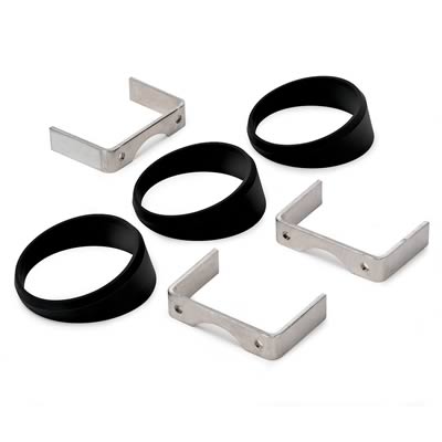
They are "angle rings" (PN ATM-3244) for 2& 5/8" gauges. I can use these to fill in the gap at the bottom of my pod, or possibly to turn the gauges towards the driver seat.
I was able to run the power supply wiring from the battery post to the E-box (8 gauge w/ 12 gauge fuse link), and the fan wiring- 8 gauge to fan 1, the MK8 fan, and 10 gauge to the BMW condenser fan relay box. All components & panels are in the E-box. I am leaving the BMW DME connector in place until I know everything is working OK on the car since the wires go to numbered pins on it. At that point, I will cut the wires and get rid of it. I picked up a large gauge starter to switch wire since the Chevy starter is on the other side of the motor from the BMW one. The alternator wire will also attach here once the motor is in.
Here are some wiring work pics:


Condenser fan relay box w/ cover on

Condenser fan relay box w/ cover off & 10 gauge wire attached through existing rubber boot

E-box with everything installed. Just a couple of more wires to go!
All I have to do now is finish the AC and datalink wiring and I can button up the E-box.
I also got the Motorcraft pigtail in place for the Hydroboost MC. I found all three leads had continuity when it was empty, and only the front & middle did when it was full, so I will wire it accordingly:
Since all pigtail wires are black, I identified them as follows:
Wire closest to front of car= #1, middle= #2, rear= #3
The BMW Brown/Green/Yellow wire connects to the #1 or 2 wire. The BMW brown (ground) wire connects to the #3 wire. When full, no continuity. When empty, continuity.
I have also installed a 16mm x 1.5 adapter to 1/2" pipe for the oil fitting that was going to go on the remote filter. Since I'm not using a remote filter anymore, I had to relocate this to the back of the block and mount it on a 3" nipple. This will supply oil pressure for the turbo, the BMW idiot light sender, and a 1/8 pipe fitting for the dash gauge. This also worked out better than expected, which is always a plus.

Box of wiring, conduit, heat shrink, and terminals
Wiring, fuse link, and fuse link to be added to 8 gauge wire for power supply
The Autogages are big- 2&5/8 diameter. The box I got for them to mount on the dash looked a lot bigger in the catalog
. I found it would not be possible to mount them with the box right side up, so I flipped it & will use it upside down. It better matches the angle of the dash and will be easier to mount & access the plumbing/wiring this way. Since I don't have a 2&5/8 hole saw, I used a 2&1/2" one and a half-round file to make up the difference. The first two holes came out great, the gauges have just enough room to mount in the panel. The third hole caused the rims of the gauges to overlap, so I ground each with my bench grinder to get a flush fit. This panel is 8.5" wide, you could not go any narrower. I was worried this would not turn out too well due to the small size of the box, but I was pleasantly surprised with the result. Can't complain for $15 and some labor.Here are some pics of the gauge work today:
Still need to plumb some -3 hose through the firewall for each gauge and run the wiring for the lighting & voltmeter.
EDIT/UPDATE 11-10-07
The silver lining in wrecking the oil pressure gauge (see below) was that I found these at Summit when I went to order another gauge:
They are "angle rings" (PN ATM-3244) for 2& 5/8" gauges. I can use these to fill in the gap at the bottom of my pod, or possibly to turn the gauges towards the driver seat.
I was able to run the power supply wiring from the battery post to the E-box (8 gauge w/ 12 gauge fuse link), and the fan wiring- 8 gauge to fan 1, the MK8 fan, and 10 gauge to the BMW condenser fan relay box. All components & panels are in the E-box. I am leaving the BMW DME connector in place until I know everything is working OK on the car since the wires go to numbered pins on it. At that point, I will cut the wires and get rid of it. I picked up a large gauge starter to switch wire since the Chevy starter is on the other side of the motor from the BMW one. The alternator wire will also attach here once the motor is in.
Here are some wiring work pics:
Condenser fan relay box w/ cover on
Condenser fan relay box w/ cover off & 10 gauge wire attached through existing rubber boot
E-box with everything installed. Just a couple of more wires to go!
All I have to do now is finish the AC and datalink wiring and I can button up the E-box.
I also got the Motorcraft pigtail in place for the Hydroboost MC. I found all three leads had continuity when it was empty, and only the front & middle did when it was full, so I will wire it accordingly:
Since all pigtail wires are black, I identified them as follows:
Wire closest to front of car= #1, middle= #2, rear= #3
The BMW Brown/Green/Yellow wire connects to the #1 or 2 wire. The BMW brown (ground) wire connects to the #3 wire. When full, no continuity. When empty, continuity.
I have also installed a 16mm x 1.5 adapter to 1/2" pipe for the oil fitting that was going to go on the remote filter. Since I'm not using a remote filter anymore, I had to relocate this to the back of the block and mount it on a 3" nipple. This will supply oil pressure for the turbo, the BMW idiot light sender, and a 1/8 pipe fitting for the dash gauge. This also worked out better than expected, which is always a plus.
Last edited by V8 Supra Builder; Nov 10, 2007 at 08:51 PM.
I spent most of the day plumbing & wiring the gauge pod. More tedious work, but it is nice having quality wire to work with. The -3 hoses were a big challenge. I ended up routing them on the passenger side through the firewall below and to the side of the E-box.
While I was there, I found an existing hole & plug. I drilled out the plug and put a small grommet there and ran the data wire for the datalink. I had to use a coat hanger to get it under the center part of the dash, but it is now routed & terminated in the E-box. I think I have like one more wire to do there, for the AC status.
I ran three 16 gauge wires from the shifter up to the gauge pod. I found everything I needed in one place there:
Switched +12V for the voltmeter
Lamp feed for lighting
Ground

The Autogauge gauges had to be individually grounded, so I made a sub harness and then tied them in as one wire using a Weather Pack terminal. The connector hooks up to the wires to the shifter area. Same thing for the lights, Autogauge gives you three red wires, I tied them in as one using a Weather Pack terminal. The pod mounts using some 1" long #4 screws into the original dash grille holes.
Mr. Brutewrench strikes again. While I was drilling out the plastic drill pod for grommets for the hoses, the bit hung up & spun the pod into the drill press post. I now have a nice ding in the oil pressure gauge trim ring. Good thing they are only like $30 each.
Here are today's pics:

Gauges almost done

Hoses/wire through firewall
While I was there, I found an existing hole & plug. I drilled out the plug and put a small grommet there and ran the data wire for the datalink. I had to use a coat hanger to get it under the center part of the dash, but it is now routed & terminated in the E-box. I think I have like one more wire to do there, for the AC status.
I ran three 16 gauge wires from the shifter up to the gauge pod. I found everything I needed in one place there:
Switched +12V for the voltmeter
Lamp feed for lighting
Ground
The Autogauge gauges had to be individually grounded, so I made a sub harness and then tied them in as one wire using a Weather Pack terminal. The connector hooks up to the wires to the shifter area. Same thing for the lights, Autogauge gives you three red wires, I tied them in as one using a Weather Pack terminal. The pod mounts using some 1" long #4 screws into the original dash grille holes.
Mr. Brutewrench strikes again. While I was drilling out the plastic drill pod for grommets for the hoses, the bit hung up & spun the pod into the drill press post. I now have a nice ding in the oil pressure gauge trim ring. Good thing they are only like $30 each.
Here are today's pics:
Gauges almost done
Hoses/wire through firewall
Last edited by V8 Supra Builder; Nov 10, 2007 at 04:58 PM.
After installing the C5 belt tensioner, I made a best guess estimate of 85.875" in length of the main belt. Using my Gates PDF catalog & their online catalog, I was able to determine an application so I could buy one locally. I found an '89 Camaro with the 2.8L V6 used an 86" belt (actually 86.375" according to Gates). I learned a while back never to go into a parts store & try & tell them what the parts are going onto. I went by Advance Auto Parts this morning after church & found the closest they had was an 86" belt (the brand they carry did not list an exact length, I got an "860K6"). I put it on & it fit, but the stretch gauge on the tensioner was all the way over:

Here is the belt installed:

I need to find a store that carries the Gates brand, or at least one that has exact lengths specified, since there is always a variation from the part number length to the actual length, i.e. my test belt is a K060930. This means it is a 6 rib belt 93" in length. Gates discloses in their catalog it is actually 93.625" long. I may also return & exchange the 86" one I bought for the next size down (855K6?).
I am now able to put the dash pieces back together since all plumbing & wiring is done. This included the datalink connector. I made a Weather Pack connector for it and powered it from a wire under the dash that was hot at all times. It grounded to a common ground point under the dash with a number of other BMW wires. I build my own datalink connectors, since the parts (housing & pins) are only like $11 shipped from a place called OBD2cables.com.

Datalink connector with Weather Pack connector

Datalink connector installed under dash
While awaiting my oil pan, I am trying to figure out how to mount the low oil level sensor. I really want to keep this function since the BMW is equipped for it and I have done the wiring needed to make it work. I am assuming the H3 oil pan will not have a port for the sensor based on the info & pics I have at this point. I have an F-body sensor, which is 20mm x 1.5 thread. My first idea was to use a bulkhead fitting & mount it through the side of the pan. I found the -12 fittings are close in size, but it takes an 18.5mm drill for them to be threaded. I ordered a tap & a bit and already have a fitting.
I also got a bulk pack of 20mm x 1.5 nuts from McMaster-Carr on a prior order. They are 16mm thick, so I think the size would be about right if they could be attached to the side of the pan. After reading about the wonders of JB Weld, I thought I would give it a shot on a scrap piece of aluminum. I drilled a .75" hole in the aluminum. I then cleaned both the nut & the aluminum and then sanded the nut with some coarse paper. I applied a ring of JB Weld under the nut, and spread what was left around the outside:

I let it dry overnight and all of this morning. I had to file some of the weld away where the sensor went in, but it did fit:

So far, so good. I then took a large bolt and hit the nut in a couple of different places while holding the aluminum. The nut snapped off after about 5 hits, so this is not a viable option. The JB Weld stuck to the steel fairly well but not so well to the aluminum.
Looks like plan A once the threading tools get here.
Since I had some extra time today, I went ahead & drilled out the passenger motor mount angle bracket. I have also picked up a one size larger AC belt for a 1998 C5, it is 42.5" long and 4 ribs. The C5 belt is 42.0" long. I won't be able to test this until the AC bracket & idler get here from Sponsor/Vendor Scoggin-Dickey.
Starter, updated
I have also mapped out wiring for the starter to retain the onboard computer's (OBC) anti-theft function. In a nutshell, the BMW starter uses 3 wires, and the GM one uses 2. I tested the wiring and found the OBC wire at the starter does not seem to do anything to prevent the starter from engaging, so for now I will tape it off. As was pointed out on the Bimmer Forum by a helpful member there, by re-routing wires to/from the trans range switch (needed to be bypassed anyway), I can avoid cutting into the starter relay wiring, and have a functional cruise/safety switch for the clutch. Here is a diagram of the concept:

Oh, and BTW the fuel pump strainer that was mailed "First Class Mail" last Tuesday from California still isn't here (USPS.com says 3 days from there to here first class), and Monday is a Federal Holiday, so hurry up & wait yet again.
Here is the belt installed:
I need to find a store that carries the Gates brand, or at least one that has exact lengths specified, since there is always a variation from the part number length to the actual length, i.e. my test belt is a K060930. This means it is a 6 rib belt 93" in length. Gates discloses in their catalog it is actually 93.625" long. I may also return & exchange the 86" one I bought for the next size down (855K6?).
I am now able to put the dash pieces back together since all plumbing & wiring is done. This included the datalink connector. I made a Weather Pack connector for it and powered it from a wire under the dash that was hot at all times. It grounded to a common ground point under the dash with a number of other BMW wires. I build my own datalink connectors, since the parts (housing & pins) are only like $11 shipped from a place called OBD2cables.com.
Datalink connector with Weather Pack connector
Datalink connector installed under dash
While awaiting my oil pan, I am trying to figure out how to mount the low oil level sensor. I really want to keep this function since the BMW is equipped for it and I have done the wiring needed to make it work. I am assuming the H3 oil pan will not have a port for the sensor based on the info & pics I have at this point. I have an F-body sensor, which is 20mm x 1.5 thread. My first idea was to use a bulkhead fitting & mount it through the side of the pan. I found the -12 fittings are close in size, but it takes an 18.5mm drill for them to be threaded. I ordered a tap & a bit and already have a fitting.
I also got a bulk pack of 20mm x 1.5 nuts from McMaster-Carr on a prior order. They are 16mm thick, so I think the size would be about right if they could be attached to the side of the pan. After reading about the wonders of JB Weld, I thought I would give it a shot on a scrap piece of aluminum. I drilled a .75" hole in the aluminum. I then cleaned both the nut & the aluminum and then sanded the nut with some coarse paper. I applied a ring of JB Weld under the nut, and spread what was left around the outside:
I let it dry overnight and all of this morning. I had to file some of the weld away where the sensor went in, but it did fit:
So far, so good. I then took a large bolt and hit the nut in a couple of different places while holding the aluminum. The nut snapped off after about 5 hits, so this is not a viable option. The JB Weld stuck to the steel fairly well but not so well to the aluminum.
Looks like plan A once the threading tools get here.
Since I had some extra time today, I went ahead & drilled out the passenger motor mount angle bracket. I have also picked up a one size larger AC belt for a 1998 C5, it is 42.5" long and 4 ribs. The C5 belt is 42.0" long. I won't be able to test this until the AC bracket & idler get here from Sponsor/Vendor Scoggin-Dickey.
Starter, updated
I have also mapped out wiring for the starter to retain the onboard computer's (OBC) anti-theft function. In a nutshell, the BMW starter uses 3 wires, and the GM one uses 2. I tested the wiring and found the OBC wire at the starter does not seem to do anything to prevent the starter from engaging, so for now I will tape it off. As was pointed out on the Bimmer Forum by a helpful member there, by re-routing wires to/from the trans range switch (needed to be bypassed anyway), I can avoid cutting into the starter relay wiring, and have a functional cruise/safety switch for the clutch. Here is a diagram of the concept:
Oh, and BTW the fuel pump strainer that was mailed "First Class Mail" last Tuesday from California still isn't here (USPS.com says 3 days from there to here first class), and Monday is a Federal Holiday, so hurry up & wait yet again.
Last edited by V8 Supra Builder; Nov 12, 2007 at 12:00 PM. Reason: Updated info
I finally got a shipment notice on the oil pan, so it should be here by the end of the week.
Since I had the passenger bracket drilled & installed, I went ahead & pulled the GTO pan & set the motor in place with the bell housing. I will need every bit of the 13" setback on the H3 pan from the looks of things. Numerous obstructions while test fitting did not help either. It looks like now the drawback may be the 7.5" deep sump vs. the rear crossmember & sway bar. I used a scrap piece of 1/4" steel for the driver side mount in the pics. I need to cut this shorter so the motor can come over towards the driver side a little, and sit back about another 1/2" to 1". I may pick up some sloped washers as well since the BMW crossmember slopes down at this point. I will also trim the 4x6 passenger side bracket when the fit is right and add some 1/4" sides to it for reinforcement.
I did have it bolted in using both brackets, but only had about 4" to the radiator, which is not enough for the MK8 fan (need like 6"). This would also skew the T56 shifter too far forward.
I measured at least 4" between the front crossmember & the bottom of the block, so there is plenty of room there. The motor is also sitting nice & low now. I had picked up a C5 alternator & it saves space over the BMW one, but since I am set up for the BMW one if I can keep it I will.
Here are some pics of the latest test fit:


Should have "plenty" of room for my passenger side turbo header, but I'm pretty sure I will have to use a block hugger on the driver side.
The wiring mod for the starter using the trans range switch was completed today & I have ordered another brake switch, a bracket, and some connectors.
Since I had the passenger bracket drilled & installed, I went ahead & pulled the GTO pan & set the motor in place with the bell housing. I will need every bit of the 13" setback on the H3 pan from the looks of things. Numerous obstructions while test fitting did not help either. It looks like now the drawback may be the 7.5" deep sump vs. the rear crossmember & sway bar. I used a scrap piece of 1/4" steel for the driver side mount in the pics. I need to cut this shorter so the motor can come over towards the driver side a little, and sit back about another 1/2" to 1". I may pick up some sloped washers as well since the BMW crossmember slopes down at this point. I will also trim the 4x6 passenger side bracket when the fit is right and add some 1/4" sides to it for reinforcement.
I did have it bolted in using both brackets, but only had about 4" to the radiator, which is not enough for the MK8 fan (need like 6"). This would also skew the T56 shifter too far forward.
I measured at least 4" between the front crossmember & the bottom of the block, so there is plenty of room there. The motor is also sitting nice & low now. I had picked up a C5 alternator & it saves space over the BMW one, but since I am set up for the BMW one if I can keep it I will.
Here are some pics of the latest test fit:
Should have "plenty" of room for my passenger side turbo header, but I'm pretty sure I will have to use a block hugger on the driver side.
The wiring mod for the starter using the trans range switch was completed today & I have ordered another brake switch, a bracket, and some connectors.
I could appreciate a foam block right about now..
I'm 99% sure I will have to run a Sanderson on the driver side. I'm going to try & finalize the mounts today. I need to pick up a piece of 3x3 angle for the driver mount and will try and "skootch" the motor about 1/2" over to the driver side & 1" back.
My AC bracket & parts came today, will need longer 10mm studs/bolts for a couple of the holes since it is being spaced away from the block.