


Retro - BiXenon E46's in a 1997 Z28.

Thread Starter
TECH Enthusiast
Joined: Jun 2004
Posts: 597
Likes: 0
Started with the factory craptastic sealed beams.
Lows
http://img.photobucket.com/albums/v2...Lowsondoor.jpg
Lows+Highs (4light system)
http://img.photobucket.com/albums/v2...shisondoor.jpg
Then got a Sealed Beam Conversion kit to allow 9006 and 9005 bulbs, hoping for better light.
Lows
http://img.photobucket.com/albums/v2...lowsondoor.jpg
Lows+Highs
http://img.photobucket.com/albums/v2...lowsondoor.jpg
Well, it did improve the situation but they just don't rock the casba.
I've had the hid kit for around two years and could just never get around to it because I only had one vehicle. Couldn't afford to take it down for weeks as i worked on getting it installed. Now with a clean garage and company truck I can use its time to get to it.
HID projectors, ballasts and all. (e46 BiXenons)
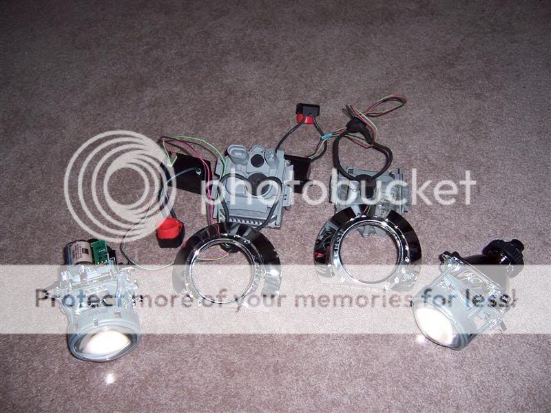
Out and Shelved the old.
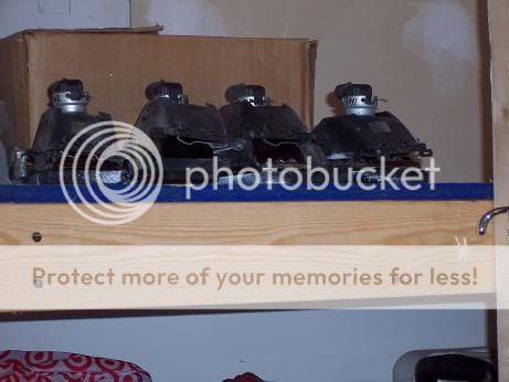
With the SBC's units and factory buckets out.
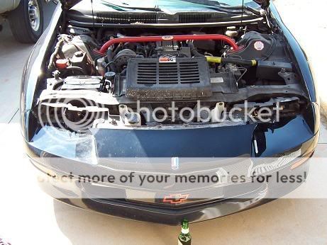
Sadly that's all the further I have gotten, migraine kicked in and forced me inside.
I hope to not have to cut any factory components so the original system can be reinstalled if ever needed. I will need to design and make a protective cover to close up the front of the headlight area. I have a sheet of lexan like material that should work, have to hold it in place somehow. I am thinking of using Mirror channel for that, paint it black and clear coat it so it should hide will. The problem is if it interferes with the beam, i will have to devise a different way. I am working in a very tight area for this installation. I think I can manage to keep all the factory stuff intact that isn't removable. Electrical power will come from a new fuse-buss and relay controlled. Don't trust the original lighting lines to supply enough power. Have to modify the projectors shroud slots to allow the shroud to be used upside down.
I found i have to put them in the High Beam location to get good side lighting, there will be significant overlap between them so there is no dark strip up the center. at 5ft from my garage door the light was starting to cross into the other headlight bays location. Using a Fuse Buss to provide power and will put in a pair of relays to trigger the lights, fortunatly their not part of the alarm systems light flash so I don't need to put a ignition controlled relay in.
16ga Wire should be enough to provide the needed amperage on a 15amp fuse. I've got a 8ga wire providing power to the Fuse Buss since i had extra of it from my stereo install.
Chevy and Bosch had to wire their headlight sockets different So i can't just plug in the stock jack, I have to use a vampire tape to get the relay trigger or find if its in the engine bay fuse box.
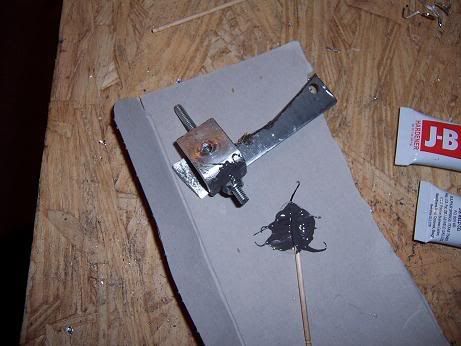
Got the mounting rig 99% done. I just have to finish grinding down a part to make it fit and JBweld some parts together. After this one is done its time to make up the other one.
I had planned on a 2 axis gimbal setup, found when i went looking I only need a single direction bracket - Vertical. Horizontal will be handled by the way i mount it to the car.
The aiming rig parts. Only one of which is used in the final version. Another was hacked up to provide other needed parts.
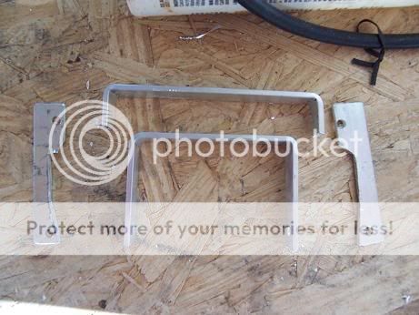
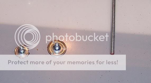
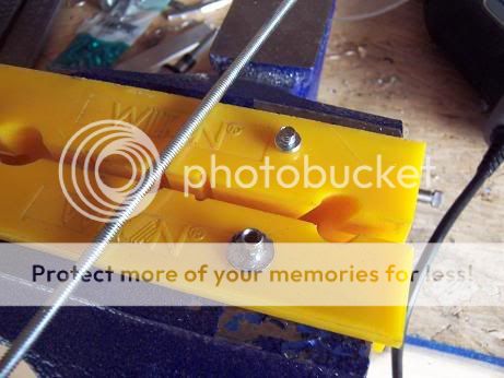
I used the larger bracket for making the Vertical aiming setup. the Longer one had its ends hacked off and used to make the two physical points for the adjustment screws. The one in the corner will have a threaded rod that is connected to a screw through a T-Nut (Threaded Rod will be JB welded to ensure it stays in place. Screw will be LocTite Blue so it can be broken free if needed.)
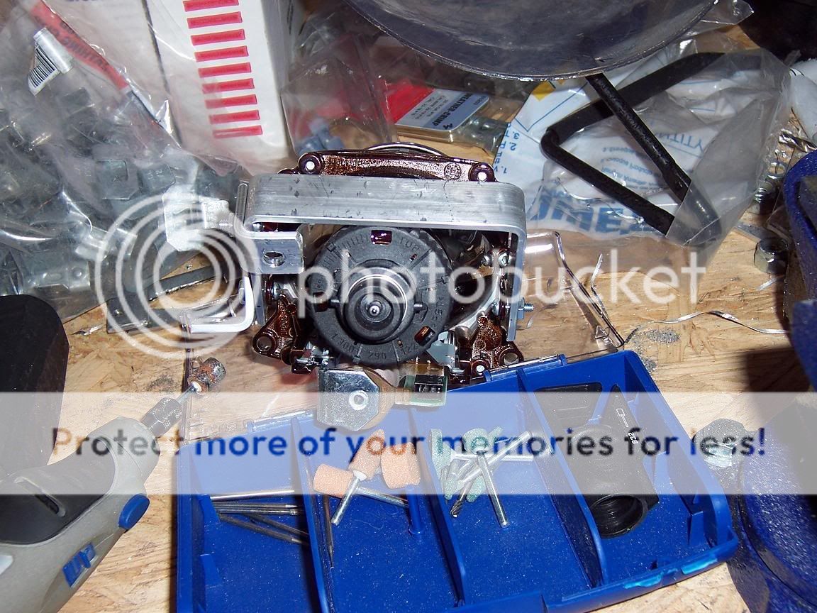
The T-Nut has to be ground down so that it has slightly less than half the flat area it does now. This will enable it to sit flush on the back of the projector housing and provide a nice collar through the hole to spin freely into the JB welded nut on the angled bracket in the rear. Nylon locknut so it should prevent the headlight from moving.
The bracket on the middle point is going to provide the horizontal aiming, by a threaded rod that is contacting the framework behind where the factory headlights were. Springs will provide enough tension so that they lights don't swing freely on the horizontal plane. The pivot point will be provided by a hole on the topsides near the corners of the top bracket and a matching hole plus a slot in the headlight frame area.
More to come tomorrow when i finish the first aiming rig. I'll give more detailed information on sizes and such as i build the second one since the first is working so well.
Lows
http://img.photobucket.com/albums/v2...Lowsondoor.jpg
Lows+Highs (4light system)
http://img.photobucket.com/albums/v2...shisondoor.jpg
Then got a Sealed Beam Conversion kit to allow 9006 and 9005 bulbs, hoping for better light.
Lows
http://img.photobucket.com/albums/v2...lowsondoor.jpg
Lows+Highs
http://img.photobucket.com/albums/v2...lowsondoor.jpg
Well, it did improve the situation but they just don't rock the casba.
I've had the hid kit for around two years and could just never get around to it because I only had one vehicle. Couldn't afford to take it down for weeks as i worked on getting it installed. Now with a clean garage and company truck I can use its time to get to it.
HID projectors, ballasts and all. (e46 BiXenons)
Out and Shelved the old.
With the SBC's units and factory buckets out.
Sadly that's all the further I have gotten, migraine kicked in and forced me inside.
I hope to not have to cut any factory components so the original system can be reinstalled if ever needed. I will need to design and make a protective cover to close up the front of the headlight area. I have a sheet of lexan like material that should work, have to hold it in place somehow. I am thinking of using Mirror channel for that, paint it black and clear coat it so it should hide will. The problem is if it interferes with the beam, i will have to devise a different way. I am working in a very tight area for this installation. I think I can manage to keep all the factory stuff intact that isn't removable. Electrical power will come from a new fuse-buss and relay controlled. Don't trust the original lighting lines to supply enough power. Have to modify the projectors shroud slots to allow the shroud to be used upside down.
I found i have to put them in the High Beam location to get good side lighting, there will be significant overlap between them so there is no dark strip up the center. at 5ft from my garage door the light was starting to cross into the other headlight bays location. Using a Fuse Buss to provide power and will put in a pair of relays to trigger the lights, fortunatly their not part of the alarm systems light flash so I don't need to put a ignition controlled relay in.
16ga Wire should be enough to provide the needed amperage on a 15amp fuse. I've got a 8ga wire providing power to the Fuse Buss since i had extra of it from my stereo install.
Chevy and Bosch had to wire their headlight sockets different So i can't just plug in the stock jack, I have to use a vampire tape to get the relay trigger or find if its in the engine bay fuse box.
Got the mounting rig 99% done. I just have to finish grinding down a part to make it fit and JBweld some parts together. After this one is done its time to make up the other one.
I had planned on a 2 axis gimbal setup, found when i went looking I only need a single direction bracket - Vertical. Horizontal will be handled by the way i mount it to the car.
The aiming rig parts. Only one of which is used in the final version. Another was hacked up to provide other needed parts.
I used the larger bracket for making the Vertical aiming setup. the Longer one had its ends hacked off and used to make the two physical points for the adjustment screws. The one in the corner will have a threaded rod that is connected to a screw through a T-Nut (Threaded Rod will be JB welded to ensure it stays in place. Screw will be LocTite Blue so it can be broken free if needed.)
The T-Nut has to be ground down so that it has slightly less than half the flat area it does now. This will enable it to sit flush on the back of the projector housing and provide a nice collar through the hole to spin freely into the JB welded nut on the angled bracket in the rear. Nylon locknut so it should prevent the headlight from moving.
The bracket on the middle point is going to provide the horizontal aiming, by a threaded rod that is contacting the framework behind where the factory headlights were. Springs will provide enough tension so that they lights don't swing freely on the horizontal plane. The pivot point will be provided by a hole on the topsides near the corners of the top bracket and a matching hole plus a slot in the headlight frame area.
More to come tomorrow when i finish the first aiming rig. I'll give more detailed information on sizes and such as i build the second one since the first is working so well.
Last edited by Nova5; Feb 12, 2009 at 07:43 PM.
Copy & Paste Moderator


Joined: Apr 2002
Posts: 9,764
Likes: 208
From: Eastern MA
Good start. I added this to the Lighting FAQ:
https://ls1tech.com/forums/appearanc...hting-faq.html
Here is the HID Planet version of this thread:
http://www.hidplanet.com/forums/viewtopic.php?t=47164
Did you say that you are putting these in the High Beam location? Why? What are you going to put in the low beam location?
https://ls1tech.com/forums/appearanc...hting-faq.html
Here is the HID Planet version of this thread:
http://www.hidplanet.com/forums/viewtopic.php?t=47164
Did you say that you are putting these in the High Beam location? Why? What are you going to put in the low beam location?
Thread Starter
TECH Enthusiast
Joined: Jun 2004
Posts: 597
Likes: 0
they will likley remain empty. I have a plastic sheet I will paint black and clearcoat to hide the whole area behind the projector lens.
In the Low Beam location I don't get enough side light from what I can tell at the close range to my garage door. It is easy to move them from one spot to another If that proves otherwise. The highbeam area is actually a little tighter than the lowbeam.
In the Low Beam location I don't get enough side light from what I can tell at the close range to my garage door. It is easy to move them from one spot to another If that proves otherwise. The highbeam area is actually a little tighter than the lowbeam.
Thread Starter
TECH Enthusiast
Joined: Jun 2004
Posts: 597
Likes: 0
Closer every day...
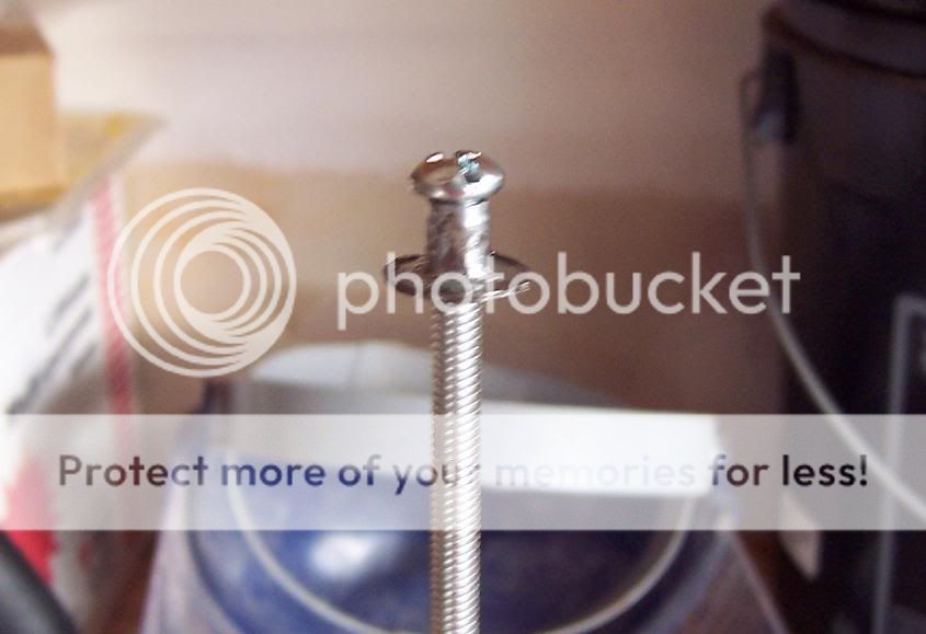
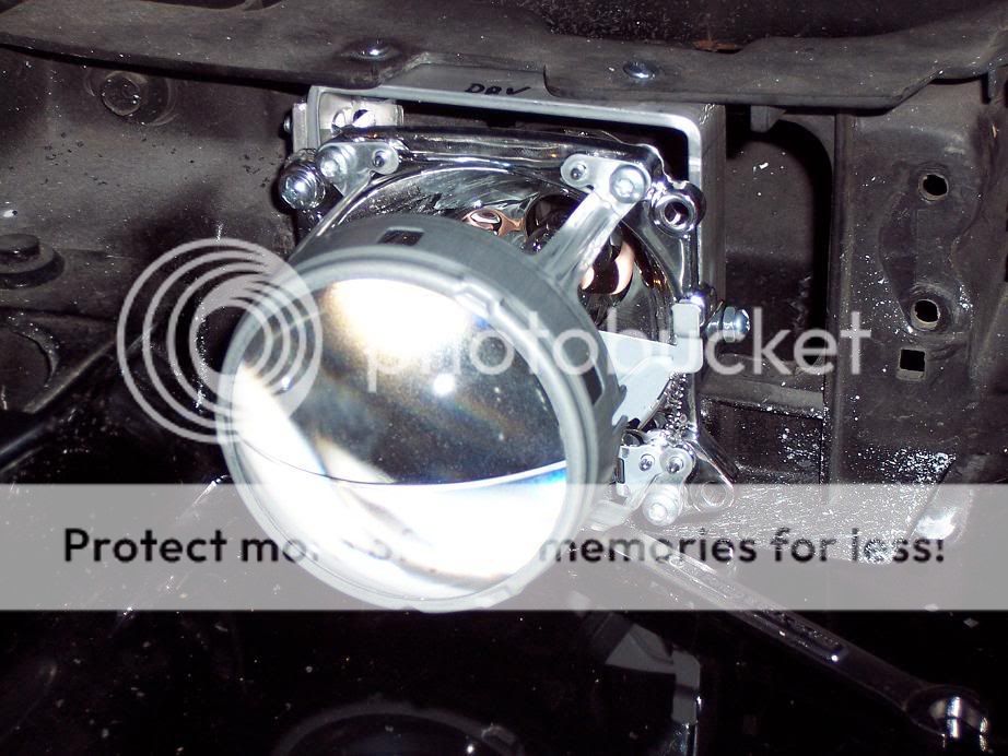
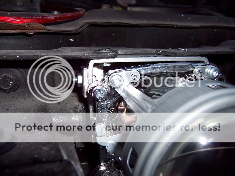
Ground the T-Nut down far enough to allow it to freely spin and not hit the projector housing. I cut a 3/8" machine screw short to provide a easy turning device.
And now its assembled. I will LocTite it in a bit.
I had to hack at the factory stuff a but, but its just extraneous crud anyway. No mounting points have been lost, just made the hole in the highbeam area bigger towards the center to allow the housing to swing for horizontal aim. FEAR THE DREMEL SABRE!
Mounted for test final test fit. Notice the screw on the far left of the projector housing, that is the adjustment rod screwhead.
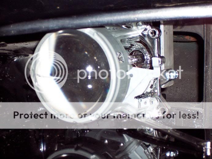

JBwelding the locknut onto the bracket.
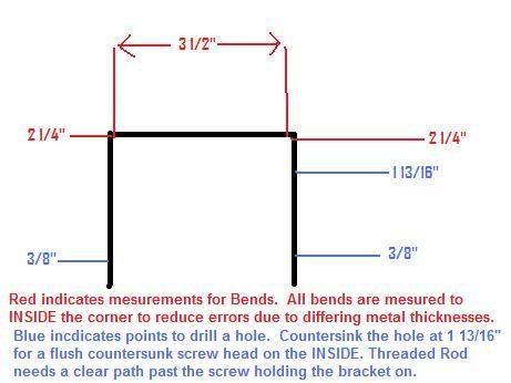
Bracket Diagram
Ground the T-Nut down far enough to allow it to freely spin and not hit the projector housing. I cut a 3/8" machine screw short to provide a easy turning device.
And now its assembled. I will LocTite it in a bit.
I had to hack at the factory stuff a but, but its just extraneous crud anyway. No mounting points have been lost, just made the hole in the highbeam area bigger towards the center to allow the housing to swing for horizontal aim. FEAR THE DREMEL SABRE!
Mounted for test final test fit. Notice the screw on the far left of the projector housing, that is the adjustment rod screwhead.
JBwelding the locknut onto the bracket.
Bracket Diagram
Last edited by Nova5; Feb 13, 2009 at 06:04 PM.
Thread Starter
TECH Enthusiast
Joined: Jun 2004
Posts: 597
Likes: 0
I ruined alot of flat bar.. about 3ft trying to get an accurate mount made. 1/8" off fouls it and makes it a trash peice. The mount itself is being made from Aluminum. Should resist rust quite well unlike bare steel! Aluminum can't be unbent like steel can. the aluminum flatbar will just snap if you try to unbend it more than a few degrees.
Thread Starter
TECH Enthusiast
Joined: Jun 2004
Posts: 597
Likes: 0
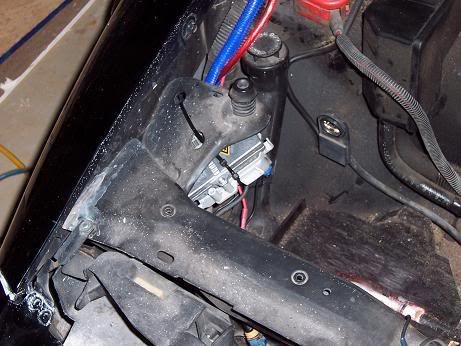
Mounted the Ballasts and Ignitors today, what fun to find hidden/non-ugly spots. One is inside the front fascia area near the marker lights. the other is near the battery in a void area there.Both spots have good weather protection. I cut a piece of plexiglass to screw the ballasts onto, I used body tape to hold the assembly to the frame where i found spots. We'll see how it holds up over time.
Factory airbox used to be in this spot seen here.
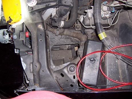 the drivers side ballast area is down inside that hole. But i found a better way to get to it than through there..
ACCESS PORT!
Cleaned up the frame area with some water and towels so the double sided body tape could hold the ballast in place.
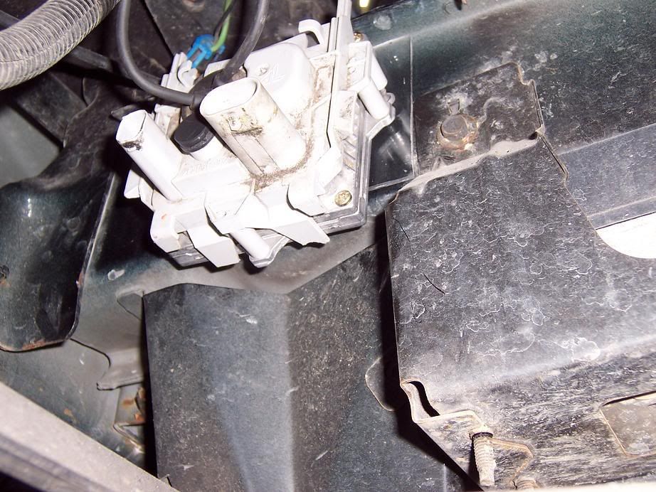
Sadley I had to mount it elsewhere on the passenger side as the horns occupy that area. So I found a spot near the battery that works and is decently non-ugly.
Ignitors are on a frame part just below and behind the highbeam bucket.
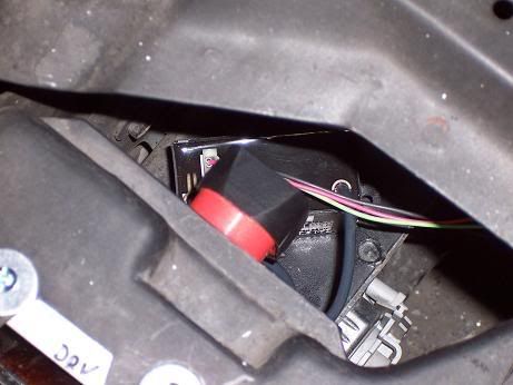
Both ballast wires can reach the ignitors from their locations.
Next is to mount the passenger side projector, get the covers, make the blocker plates and modify the other shroud to fit, run the electric from the battery fuse buss up to the ballasts, wire up the relays... hopefully all done by this weekend except the covers (shipping time!)
Factory airbox used to be in this spot seen here.
the drivers side ballast area is down inside that hole. But i found a better way to get to it than through there..ACCESS PORT!
Cleaned up the frame area with some water and towels so the double sided body tape could hold the ballast in place.
Sadley I had to mount it elsewhere on the passenger side as the horns occupy that area. So I found a spot near the battery that works and is decently non-ugly.
Ignitors are on a frame part just below and behind the highbeam bucket.
Both ballast wires can reach the ignitors from their locations.
Next is to mount the passenger side projector, get the covers, make the blocker plates and modify the other shroud to fit, run the electric from the battery fuse buss up to the ballasts, wire up the relays... hopefully all done by this weekend except the covers (shipping time!)
Last edited by Nova5; Feb 18, 2009 at 07:42 PM.
Trending Topics
Thread Starter
TECH Enthusiast
Joined: Jun 2004
Posts: 597
Likes: 0
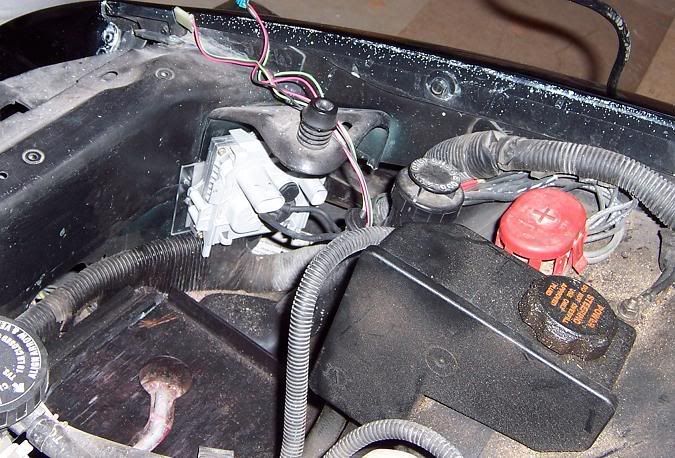
Tape failed to hold against silly human tugging on the 8ga power wire to get a little more slack.
So now its zip tied to the passenger side hood stop bracket. I may end up moving the drivers side to the same not so nice location Or just find a way to tie it up in that void i have it in.
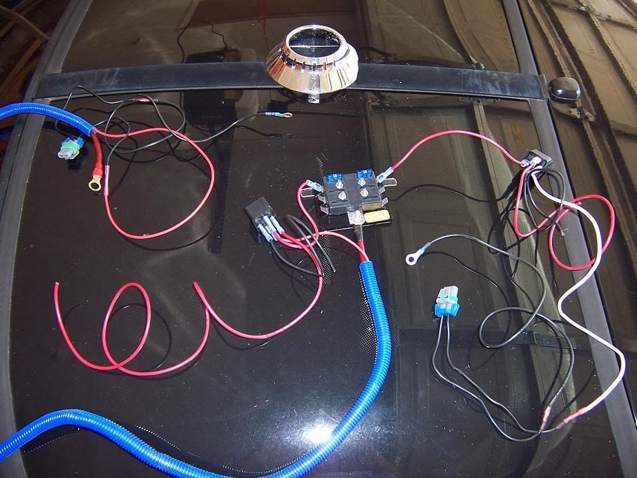
Built the wiring harness last night. Nice little fuse buss with a 8ga wire to provide it power for anything i may later add. relays triggered from the low beam headlight 12v wire. used a set of vampire taps to bite into it and gain the switch source that way. The passenger light is supplied power by a 16ga wire running in the same loom as the 8ga supply.
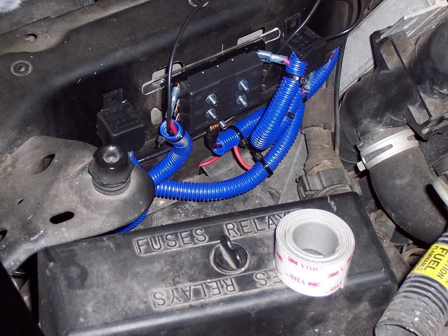
Installed and fully loomed.
And if its not one thing its another.. I now have to replace my battery tray as its front hold lip is busted off.
So now its zip tied to the passenger side hood stop bracket. I may end up moving the drivers side to the same not so nice location Or just find a way to tie it up in that void i have it in.
Built the wiring harness last night. Nice little fuse buss with a 8ga wire to provide it power for anything i may later add. relays triggered from the low beam headlight 12v wire. used a set of vampire taps to bite into it and gain the switch source that way. The passenger light is supplied power by a 16ga wire running in the same loom as the 8ga supply.
Installed and fully loomed.
And if its not one thing its another.. I now have to replace my battery tray as its front hold lip is busted off.
LS1 Tech Stories
The Best V8 Stories One Small Block at Time

Topdon ONE vs. Artidiag 800 BT2: Which is the Diagnostic Tablet For You?
Pouria Savadkouei
Gas Monkey Built a 6-Wheel Ferrari Testarossa With a Corvette LT4 Engine
Verdad Gallardo
7 Most Reliable High-Performance Engines GM Has Ever Built
Verdad Gallardo
Amazing '71 Camaro Restomod Is Modern Muscle Car Under the Skin
Verdad Gallardo
6 Common C5 Corvette Failures and What's Involved In Repairing Them
Pouria Savadkouei
Retro Modern Bandit Pontiac Trans AM Comes With Burt Reynolds' Autograph
Verdad Gallardo
Top 10 Greatest Cadillac V Series Performance Models Ever, Ranked
Pouria Savadkouei
Top 10 Most Powerful Chevy Trucks Ever Made!

Hennessey's New Supercharged Silverado ZR2 Has 700 HP
Verdad Gallardo

looks good so far. ill be keeping an eye on this one. have you seen my thread, i know its for a 98-02 camaro, but projector threads are fun...
https://ls1tech.com/forums/western-m...ave-again.html
https://ls1tech.com/forums/western-m...ave-again.html
Thread Starter
TECH Enthusiast
Joined: Jun 2004
Posts: 597
Likes: 0
I haven't had time to do anything to it lately. I found more broken stuff. Battery tray, Horns, passenger signal light housing is burned, paint chipping on my hood in a hard to work corner. fun fun! ALong with getting a house ready for closing I just sadley haven't had time. This weekend should allow me to finish up the retro and fix everything supposing my parts arrive.
Thread Starter
TECH Enthusiast
Joined: Jun 2004
Posts: 597
Likes: 0
Finally got it back from the paint shop.
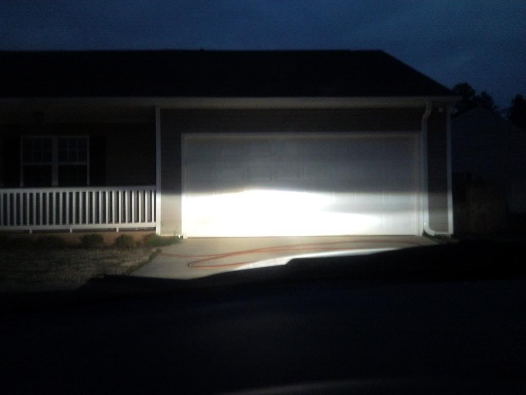
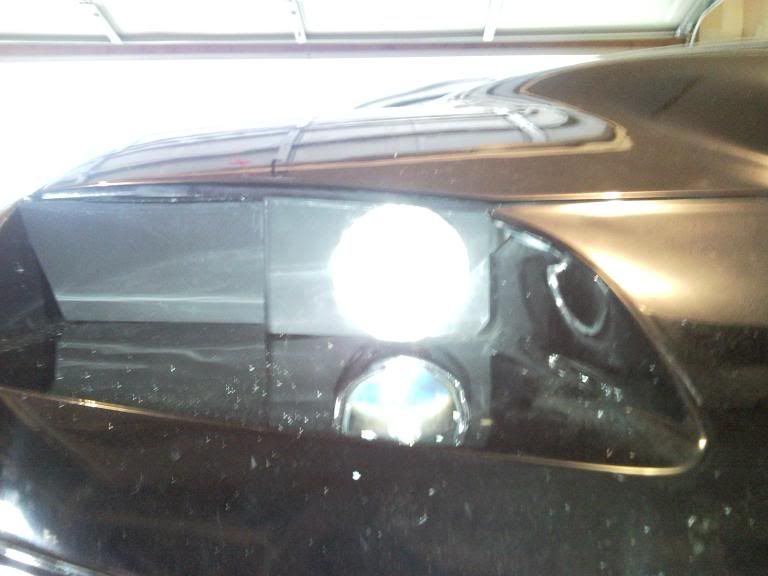
First test firing.
They work! Now to finalize everything... I have to build the back blocker plate for the drivers side and finish the one for the passenger side, its only roughly built at the moment. Still need to shave down the top so the hood can close.
Need to install the light covers on the front of the light bay openings. I have to repair the adjustment rod setup for the passenger side. I didnt run the rod in far enough on the backside so when i turned the screw head I broke the threadlocker's bond. I must not have used enough Lock Tite on it. ahhwell. any project like this is loaded with interesting hurdles and minor problems!
Thread Starter
TECH Enthusiast
Joined: Jun 2004
Posts: 597
Likes: 0
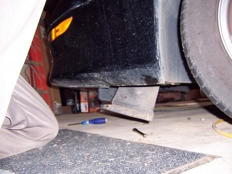
After alot of time and some failed experiments I found something that will work for a shroud.
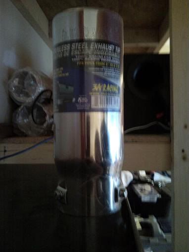
And even better its rated for heat!
These are the parts left over after I hacked it up. The first cut was to cut off the back end and extract the innards. Fortunately the pretty opening just has the innards pressed against it. Saved me from having to cut inside the tip. The second cut was to cut the needed end off the tube. I put a line around the tip at 1 5/8" from the tip. I managed this by using a scrap of lexan that was my test peice for heating up and bending. Drilled a hole through it, slipped the sharpie point in and turned the exhaust tip while in contact.
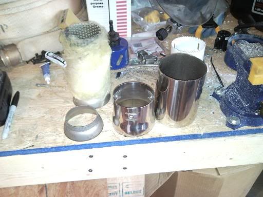
Test fitting the backer plate and shroud. Backer is only primered at this point. I have some gloss blank engine paint to finish it off with. It still needs a bit of work to align and seal. Also have yet to figure out a good way to mount the shroud to the projector.
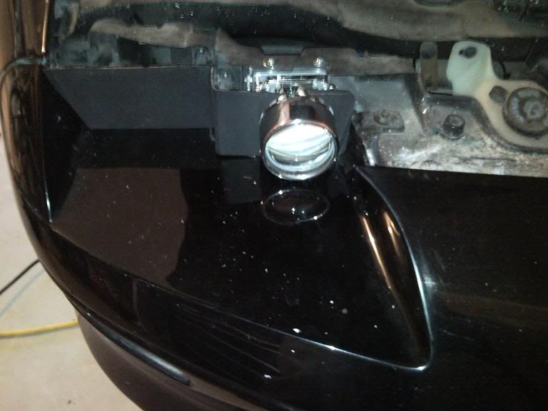
Closed the hood.. I need to drop the projector body more, damn thing is STILL to high, even though the beam is at a good aim the lens body is to close to the hood.
And even better its rated for heat!
These are the parts left over after I hacked it up. The first cut was to cut off the back end and extract the innards. Fortunately the pretty opening just has the innards pressed against it. Saved me from having to cut inside the tip. The second cut was to cut the needed end off the tube. I put a line around the tip at 1 5/8" from the tip. I managed this by using a scrap of lexan that was my test peice for heating up and bending. Drilled a hole through it, slipped the sharpie point in and turned the exhaust tip while in contact.
Test fitting the backer plate and shroud. Backer is only primered at this point. I have some gloss blank engine paint to finish it off with. It still needs a bit of work to align and seal. Also have yet to figure out a good way to mount the shroud to the projector.
Closed the hood.. I need to drop the projector body more, damn thing is STILL to high, even though the beam is at a good aim the lens body is to close to the hood.
Thread Starter
TECH Enthusiast
Joined: Jun 2004
Posts: 597
Likes: 0
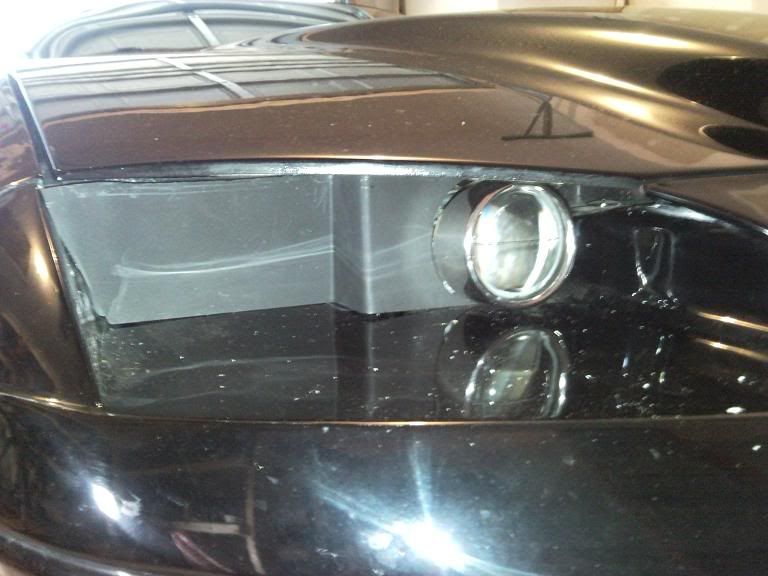
Almost there! I just have to wait on the paint to dry on the drivers side back plate, cut the shroud for it, shave down the friction ring and put on the cover!
Passenger side is assembled and road worthy! I will need to devise a gasket or rain shield to bridge between the hood and front cover. Since this car has had a front end impact its not quite perfect.
Here she is!


The shroud is held on by a friction ring made from a 3" sewer (3034) pipe female adapter. Cut the slip fit side off at the right size to fit in the exhaust tip shroud, I did have to take a section of the ring out so its a open loop. Used a sanding drum on the dremel to thin it up enough for the shroud to slide on with a bit of a push.
Passenger side is assembled and road worthy! I will need to devise a gasket or rain shield to bridge between the hood and front cover. Since this car has had a front end impact its not quite perfect.
Here she is!
The shroud is held on by a friction ring made from a 3" sewer (3034) pipe female adapter. Cut the slip fit side off at the right size to fit in the exhaust tip shroud, I did have to take a section of the ring out so its a open loop. Used a sanding drum on the dremel to thin it up enough for the shroud to slide on with a bit of a push.
Last edited by Nova5; Apr 4, 2009 at 08:24 PM.
nice work!
personally, i would have put the projector where the lower beam was originally to keep the "wide" look while they are on at night. But i am sure you have your reasons for doing what you did. Great job!
personally, i would have put the projector where the lower beam was originally to keep the "wide" look while they are on at night. But i am sure you have your reasons for doing what you did. Great job!

that looks great. i like the shroud idea. going to have to do something like that when i install my hella's. i wish there was a better way to mount those clear gts covers, guess that will have to do.